MCU architecture
UAT 204 Microcontrollers and Embedded Systems
Lesson
By the end of this module you will be able to
- Explain the parts of a microcontroller - CPU, memory, bus and peripherals
- Compare the microcontrollers in a Pixhawk 6X flight controller, a Pico 2 and an ESP32-S3
- Calculate ADC resolution and convert a digital reading back to voltage
- Design a voltage divider to measure battery voltage with an ADC
Why this matters
A single drone contains several small computers: the flight controller, every ESC, the GPS and even some smart batteries each have their own microcontroller (MCU). An MCU is a whole computer shrunk into one chip, CPU, memory and interface circuits together, designed to do specific jobs with guaranteed timing, low power and low cost, unlike general-purpose computers that can do many things but guarantee no timing.
The whole course uses one hypothetical case: building an add-on sensor module for a drone on a Raspberry Pi Pico 2 that reads sensors, measures voltage, drives a servo and sends data to the flight controller. The Python code of every module can be downloaded from /downloads/uat-204/.
Inside a microcontroller
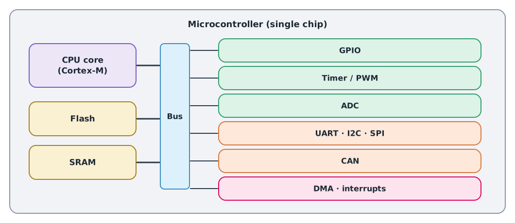
- The CPU core executes instructions; most MCUs in drone work use Arm Cortex-M cores
- Flash stores the program and constants, and keeps them when powered off
- SRAM holds variables while running, and loses them when powered off
- The bus carries data between all parts
- Peripherals are dedicated circuits on the chip, such as GPIO (digital inputs and outputs), timers, the ADC (analog-to-digital converter) and communication circuits, which work alongside the CPU
MCUs in drone work
| Board | MCU | Strengths |
|---|---|---|
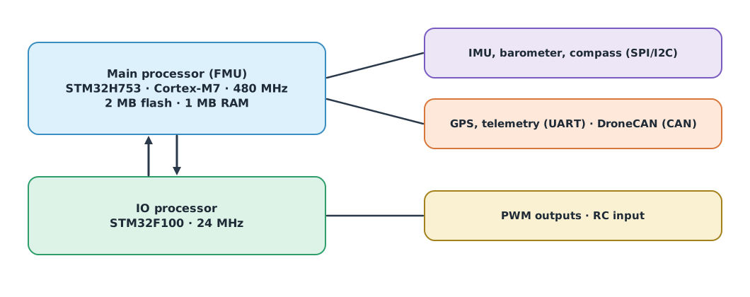
| Pixhawk 6X (flight controller) | STM32H753 Cortex-M7 at 480 MHz, 2 MB flash, 1 MB RAM, plus an STM32F100 IO processor | Offloads outputs to a second processor |
| Raspberry Pi Pico 2 (lab) | RP2350, dual Cortex-M33 (or RISC-V) at 150 MHz, 520 KB SRAM | Cheap, 12-bit ADC, 16 PWM channels |
| ESP32-S3 | Dual Xtensa LX7 at 240 MHz, 512 KB SRAM | Built-in Wi-Fi and Bluetooth |
All figures come from the PX4, Raspberry Pi and Espressif documentation. Flight controllers use faster MCUs with more memory because they must estimate state and control attitude hundreds of times a second.
The ADC: from voltage to numbers
An ADC (analog-to-digital converter) turns a voltage into an integer. An -bit ADC divides 0 to into steps, each called an LSB. The RP2350 has a 12-bit ADC, so 4,096 steps.
An ADC pin can take no more than the chip’s reference voltage (about 3.3 V), but a 6S battery reaches 25.2 V, so it must first be reduced with a voltage divider.
Example 1 Measuring a 6S battery with a 12-bit ADC
Resistors kΩ and kΩ, reference voltage 3.3 V.
vref, bits = 3.3, 12
lsb = vref / 2 ** bits
r1, r2 = 100_000, 10_000
ratio = r2 / (r1 + r2)
print(f"LSB = {lsb * 1000:.3f} mV at the pin = {lsb / ratio * 1000:.2f} mV of battery voltage")
for v_batt in (25.2, 22.2, 19.8):
    v_pin = v_batt * ratio
    code = round(v_pin / lsb)
    print(f"battery {v_batt:5.1f} V -> pin {v_pin:.3f} V -> code {code:4d} -> read back {code * lsb / ratio:.3f} V")
LSB = 0.806 mV at the pin = 8.86 mV of battery voltage
battery 25.2 V -> pin 2.291 V -> code 2844 -> read back 25.204 V
battery 22.2 V -> pin 2.018 V -> code 2505 -> read back 22.200 V
battery 19.8 V -> pin 1.800 V -> code 2234 -> read back 19.798 VA full 25.2 V battery puts about 2.29 V on the pin, safely below 3.3 V. Each ADC step equals about 8.9 mV of battery voltage. Real accuracy also depends on resistor tolerance, noise and reference accuracy, so calibrate against a multimeter as in UAT 321.
Module lab
Lab: getting to know the Pico 2
- Read the Pico 2 pinout and identify GPIO pins, ADC pins, 3.3 V and ground.
- Install the programming tools (MicroPython or the C/C++ SDK, as the instructor directs) and write an LED blink program.
- Build the voltage divider on a breadboard, using an adjustable supply instead of a battery (no higher than the calculated safe value), and read the ADC at three voltages.
- Compare readings with the code in Example 1 and a multimeter, and find a calibration factor.
- Open the Pixhawk 6X page in the PX4 documentation and identify which processor each sensor and port connects to.
Common mistakes
Watch out
- Applying more than 3.3 V to an ADC or GPIO pin, which may destroy the chip at once
- Forgetting a common ground between the measured circuit and the MCU
- Trusting ADC readings without calibration
- Choosing an MCU by CPU speed alone without checking the peripherals needed
- Assuming SRAM contents survive power-off
Summary
- An MCU combines CPU, memory, bus and peripherals on one chip, doing specific jobs with guaranteed timing
- The Pixhawk 6X uses an STM32H753 as its main processor and an STM32F100 as its IO processor
- An -bit ADC divides the voltage range into steps
- Measure high voltages through a voltage divider, and calibrate
Check your understanding
- What is the resolution of a 10-bit ADC with a 3.3 V reference, in mV?
- A divider with kΩ and kΩ has 16.8 V in. What is the pin voltage?
- A 12-bit ADC with a 3.3 V reference reads 2048. What is the pin voltage?
- Which loses its data at power-off, Flash or SRAM?
- Which MCU is the Pixhawk 6X main processor?
Answers
- mV
- V
- V
- SRAM
- STM32H753 (Cortex-M7 at 480 MHz)
Key formulas
| ADC resolution | |
| Voltage divider |
Key references
Further reading
Study the assigned knowledge units in advance, review media and take the module quiz
In class / field
Lab or field practice from worksheets with a safety checklist
Learning evidence: Checked worksheets and quiz results