Automation and drones
UAT 202 Fundamentals of Automation Technology
Lesson
By the end of this module you will be able to
- Design the battery-swap station's sequence as a state machine with fault handling
- Explain Modbus TCP communication and build a request to read holding registers
- Explain the cascaded controllers in PX4 and ArduPilot flight controllers
- Use ArduPilot relays and grippers to connect a drone with automated equipment
Why this matters
A drone that must patrol an area all day needs its battery swapped regularly. Swapping by hand means someone on duty at all times, so an automatic battery-swap station is where industrial automation (sensors, PLCs, actuators) meets the drone system (flight controller, missions and links). This module brings the whole course together.
The sequence as a state machine
A state machine describes a system as a set of states, and the events that move it from one state to another. The SFC language in IEC 61131-3 is designed for this kind of task.
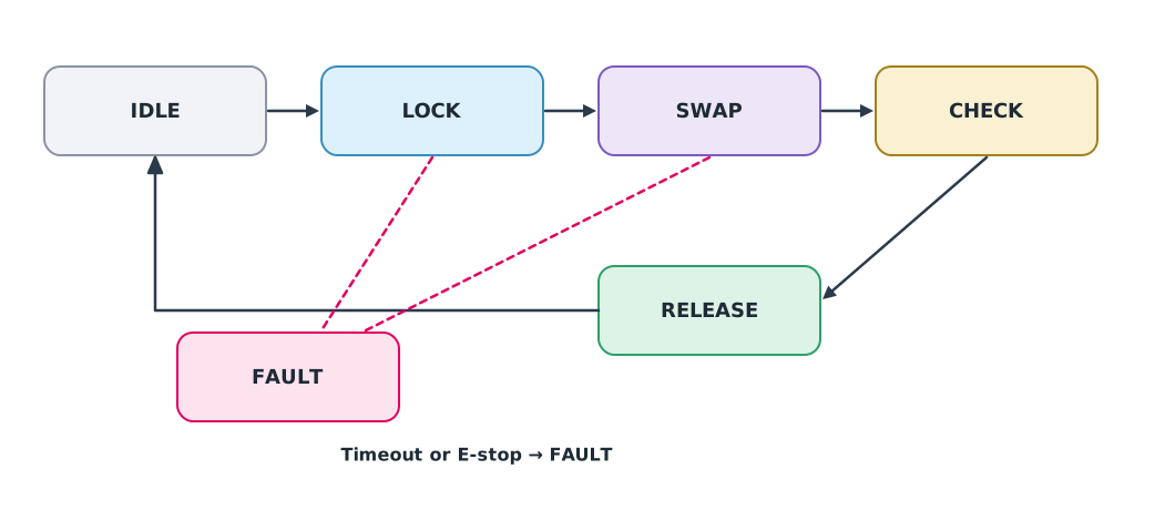
- IDLE: wait for a drone to land
- LOCK: clamp the drone in position when the sensor sees it on the pad
- SWAP: the gripper removes the old battery and inserts a new one
- CHECK: confirm the new battery is seated and its voltage is correct
- RELEASE: unclamp, leaving the drone ready to take off
- FAULT: if any step times out or the emergency stop is pressed, stop all motion and wait for a person to inspect
Example 1 Simulating the station’s state machine
TIMEOUT = {"LOCK": 5, "SWAP": 20, "CHECK": 5, "RELEASE": 5}   # maximum seconds per state
NEXT = {("IDLE", "landed"): "LOCK", ("LOCK", "locked"): "SWAP", ("SWAP", "swapped"): "CHECK",
        ("CHECK", "voltage_ok"): "RELEASE", ("RELEASE", "released"): "IDLE"}


def run(events):
    state, entered = "IDLE", 0
    for t, event in events:
        if event == "estop" or (state in TIMEOUT and t - entered > TIMEOUT[state]):
            reason = "E-stop" if event == "estop" else f"timeout in {state}"
            print(f"t={t:>3} s  {state:<8} -> FAULT ({reason})")
            return "FAULT"
        new = NEXT.get((state, event))
        if new:
            print(f"t={t:>3} s  {state:<8} -> {new:<8} on '{event}'")
            state, entered = new, t
    return state


print("final:", run([(0, "landed"), (2, "locked"), (15, "swapped"), (17, "voltage_ok"), (19, "released")]))
print("final:", run([(0, "landed"), (2, "locked"), (30, "swapped")]))
t= 0 s IDLE -> LOCK on 'landed'
t= 2 s LOCK -> SWAP on 'locked'
t= 15 s SWAP -> CHECK on 'swapped'
t= 17 s CHECK -> RELEASE on 'voltage_ok'
t= 19 s RELEASE -> IDLE on 'released'
final: IDLE
t= 0 s IDLE -> LOCK on 'landed'
t= 2 s LOCK -> SWAP on 'locked'
t= 30 s SWAP -> FAULT (timeout in SWAP)
final: FAULTThe first run swaps the battery in 19 s. In the second, the gripper exceeds its 20 s limit, so the station goes to FAULT rather than releasing a drone whose battery may not be seated. Setting a maximum time for every state stops the system hanging without anyone knowing.
Modbus: a common language for devices
The drone mission system must ask the station’s PLC whether it is ready. Modbus is a widely used industrial protocol, storing data as coils (bits) and registers (16-bit values). Under Modbus specification V1.1b3, the TCP variant uses port 502, function 01 reads coils and function 03 reads holding registers. OPC UA (IEC 62541) is a newer standard with richer data structures and security.
Example 2 Building a Modbus TCP request
Read two holding registers starting at address 0 (such as station status and the number of ready batteries) from device 1.
import struct

transaction_id, protocol_id, unit_id = 1, 0, 1
function_code, start_address, quantity = 3, 0, 2
pdu = struct.pack(">BHH", function_code, start_address, quantity)   # function + data
mbap = struct.pack(">HHHB", transaction_id, protocol_id, len(pdu) + 1, unit_id)
frame = mbap + pdu
print("request bytes:", frame.hex(" "))
print("length:", len(frame), "bytes; send to TCP port 502")
request bytes: 00 01 00 00 00 06 01 03 00 00 00 02
length: 12 bytes; send to TCP port 502The first six bytes are the MBAP header (transaction number, protocol and length), followed by the unit number, then function 03, the start address and the quantity. Classic Modbus has no authentication or encryption, so it must stay on an isolated network with controlled access and never be exposed to the internet.
Automation inside the drone
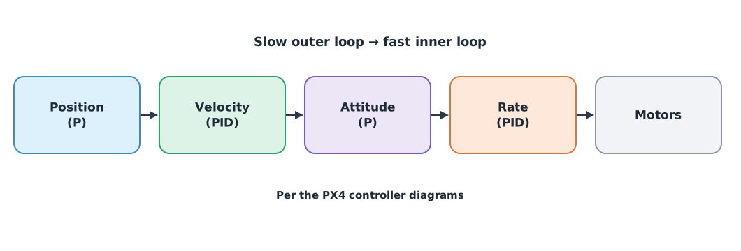
A flight controller uses several nested feedback loops (a cascade). In PX4’s diagrams, the position loop commands velocity, the velocity loop commands attitude, the attitude loop commands rotation rate, and the rate loop commands the motors, with inner loops running faster than outer ones. ArduPilot follows the same principle: an angle P controller produces a desired rate, and a rate PID controller drives the motors.
A drone can also command external equipment. ArduPilot has relays triggered by a transmitter switch or the DO_SET_RELAY mission command, and a servo gripper commanded with DO_GRIPPER, for example to release a load at the destination. This is the same automation studied throughout the course, just on an aircraft.
Module lab
Lab: designing the battery-swap station
- Write the station’s state machine in SFC or ST in CODESYS following Figure 1, with a maximum time for every state.
- Test the normal case, a timeout in every state and an emergency stop, comparing with Example 1.
- Enable a Modbus TCP server in CODESYS and read the registers from a computer on the lab’s internal network.
- In ArduPilot SITL, configure a relay and issue
DO_SET_RELAYin a mission, checking its state in the log. - Draw an overall diagram of how the drone, station and mission system communicate, and where emergency stops are needed.
Common mistakes
Watch out
- Not setting a maximum time per state, so the system waits forever for an event that never comes
- Leaving FAULT automatically without a person inspecting
- Exposing Modbus to outside networks when it has no authentication
- Tuning the outer loop of a cascade before the inner loop, when the inner loop must be stable first
- Testing relays or grippers on a real aircraft with propellers fitted
Summary
- A state machine describes a sequence as states and events, and needs time limits and a FAULT state
- Modbus TCP uses port 502 and function 03 reads holding registers, on a controlled network
- A flight controller is a cascade of feedback loops from position down to rotation rate
- ArduPilot can command relays and grippers from missions, linking drones with automated equipment
Check your understanding
- The SWAP state has a 20 s limit and was entered at 2 s. If it has not finished at 25 s, what happens?
- Which Modbus function reads holding registers?
- Which port does Modbus TCP use?
- In a cascaded controller, which loop runs fastest?
- Which ArduPilot mission command operates a gripper?
Answers
- More than 20 s have passed (23 s), so it goes to FAULT
- Function 03
- Port 502
- The rate loop, the innermost
DO_GRIPPER
Key formulas
| State transition |
Key references
- Modbus Organization. (2012). MODBUS application protocol specification V1.1b3. link
- PX4 Autopilot. Controller diagrams. PX4 user guide (main). link
- ArduPilot Dev Team. Copter attitude control. ArduPilot developer documentation. link
- ArduPilot Dev Team. Relay switch. ArduPilot Copter documentation. link
- ArduPilot Dev Team. Servo gripper. ArduPilot Copter documentation. link
- International Electrotechnical Commission. (2025). OPC unified architecture – Part 1: Overview and concepts (IEC 62541-1:2025). link
- International Organization for Standardization. (2015). Safety of machinery — Emergency stop function — Principles for design (ISO 13850:2015). link
Further reading
Study the assigned knowledge units in advance, review media and take the module quiz
Topic 2: AI and automated control
Deep dive: from embedded systems to AI robots and ROS
Cascade control and flight-controller tuning
Deep dive: MQTT and Eclipse Mosquitto for drone and IoT systems
In class / field
Lab or field practice from worksheets with a safety checklist
Learning evidence: Checked worksheets and quiz results