Introductory feedback control
UAT 202 Fundamentals of Automation Technology
Lesson
By the end of this module you will be able to
- Explain ON/OFF control with hysteresis and why it oscillates
- Explain the roles of the P, I and D terms of a PID controller
- Simulate a temperature loop and compare ON/OFF, P and PI by steady-state error and oscillation
- Explain integral windup and a basic way to prevent it
Why this matters
Lithium batteries charged in heat wear quickly and risk becoming dangerous, so the swap station’s charging cabinet must hold its temperature with a cooling fan. Ways of commanding the fan range from the simplest, on when hot and off when cool, to a PID controller that adjusts fan power continuously. The same principle is used in a drone’s flight controller, holding attitude hundreds of times a second.
The feedback block diagram
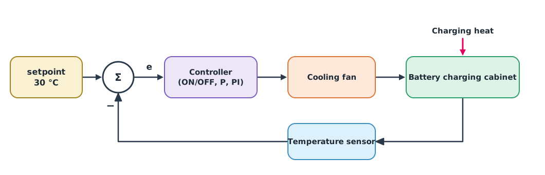
A simple cabinet model: charging heat warms it, the fan removes up to , and the walls exchange heat with the surrounding air at rate . With no fan at all, the temperature settles at , here °C, which is far too hot.
ON/OFF, P, I and D
- ON/OFF runs the fan at full when too hot and off when cool enough. It needs hysteresis (a dead band), such as on above 30.5 °C and off below 29.5 °C; otherwise the fan switches so often it wears out. The temperature therefore always oscillates within that band
- P (proportional) commands in proportion to the present error: the hotter, the harder the fan runs. It usually leaves a steady-state error, because some error must remain to keep the fan running
- I (integral) accumulates the error over time. As long as an error remains, the command keeps rising until the steady-state error disappears
- D (derivative) looks at the rate of change of the error, helping reduce overshoot, but is sensitive to noise; slow temperature processes often omit D
Example 1 Comparing ON/OFF, P and PI
The cabinet starts at 32 °C and should be 30 °C. Simulate one hour in 1 s steps, with the fan command between 0 and 1.
def cabinet(mode, kp=0.3, ki=0.002, t_end=3600, dt=1.0):
    C, h, Ta, Q, Pmax, sp = 20000.0, 10.0, 32.0, 300.0, 600.0, 30.0   # J/K, W/K, °C, W, W, °C
    temp, integ, on, switches, hist = 32.0, 0.0, False, 0, []
    for _ in range(int(t_end / dt) + 1):
        e = temp - sp                                    # positive when too hot
        if mode == "ON/OFF":
            new_on = True if temp > sp + 0.5 else False if temp < sp - 0.5 else on
            switches += new_on != on
            on = new_on
            u = 1.0 if on else 0.0
        elif mode == "P":
            u = min(max(kp * e, 0.0), 1.0)
        else:                                            # PI, not integrating while saturated
            integ += e * dt
            raw = kp * e + ki * integ
            u = min(max(raw, 0.0), 1.0)
            if u != raw:
                integ -= e * dt
        temp += dt * (Q - Pmax * u - h * (temp - Ta)) / C
        hist.append(temp)
    last = hist[-1200:]                                  # the last 20 minutes
    return min(last), max(last), switches


for mode in ("ON/OFF", "P", "PI"):
    lo, hi, sw = cabinet(mode)
    print(f"{mode:<6} last 20 min: {lo:.2f}–{hi:.2f} °C" + (f", fan switched {sw} times" if mode == "ON/OFF" else ""))
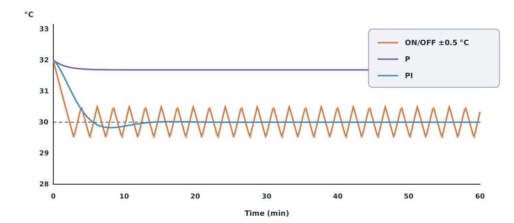
ON/OFF last 20 min: 29.50–30.51 °C, fan switched 52 times
P last 20 min: 31.68–31.68 °C
PI last 20 min: 30.00–30.00 °CON/OFF oscillates around 30 °C and the fan switches dozens of times an hour. P does not oscillate but settles about 1.7 °C above the target. PI settles exactly at 30 °C, because the I term keeps raising the command until the error is gone.
Integral windup
If the command saturates, for example the fan is already at full but it is still too hot, the I term keeps accumulating with no effect. When the temperature reaches the target, the excess accumulation keeps the fan on until it is too cold. This is integral windup. The example prevents it the simplest way, by pausing accumulation while the command is saturated. PX4’s flight controller also limits the I term in its rate loop.
Module lab
Lab: tuning a temperature controller
- Run the code in Example 1, change the ON/OFF band to ±0.2 and ±1.0 °C, and record the number of fan switches and the oscillation range.
- Raise the P controller’s to 0.6 and 1.2, record the steady-state error, and explain why it never fully disappears.
- Remove the line that pauses I accumulation and start from a 45 °C cabinet, comparing with the windup-protected version.
- With a training rig, use a real temperature sensor and fan through a PLC or microcontroller, write ON/OFF with hysteresis, and record the response.
- Conclude which controller the station’s charging cabinet should use, with reasons.
Common mistakes
Watch out
- Using ON/OFF without hysteresis, so equipment switches rapidly and wears out
- Raising to chase steady-state error until the system oscillates
- Not preventing integral windup when the command saturates
- Adding a D term to a noisy signal
- Tuning a real system without safety limits, such as cutting charging when overheated
Summary
- ON/OFF is simple but always oscillates, and needs hysteresis
- P reduces error but usually leaves a steady-state error; I removes it; D reduces overshoot but is noise-sensitive
- PI suits slow processes such as temperature
- Integral windup must be prevented when the command saturates
Check your understanding
- A cabinet has °C, W and W/K. Without a fan, where does its temperature settle?
- A P controller has and an error of 2 °C. What is the command?
- Which PID term removes steady-state error?
- Why does ON/OFF need hysteresis?
- When does integral windup occur?
Answers
- °C
- The I term
- So equipment does not switch too often when the value is near the target
- When the command is saturated but error remains, so the I term keeps accumulating without effect
Key formulas
| PID controller | |
| Charging cabinet model | |
| Steady temperature without cooling |
Key references
Further reading
Study the assigned knowledge units in advance, review media and take the module quiz
In class / field
Lab or field practice from worksheets with a safety checklist
Learning evidence: Checked worksheets and quiz results