GPIO, timers, interrupts and PWM
UAT 204 Microcontrollers and Embedded Systems
Lesson
By the end of this module you will be able to
- Configure GPIO pins as inputs or outputs with pull-up or pull-down
- Calculate timer prescaler and auto-reload values to generate PWM at a required frequency
- Generate servo and ESC pulse widths following ArduPilot's default ranges
- Compare polling with interrupts and debounce a button
Why this matters
Everything an MCU does with the outside world starts at its pins: reading buttons and sensor signals, driving LEDs, and commanding servos or ESCs with pulses accurate to microseconds. Counting time with the CPU is inaccurate and wastes time needed for other work, so MCUs have timers that generate pulses by themselves, and interrupts that wake the CPU when something happens.
GPIO
A GPIO (general-purpose input/output) pin can be set as an input or output. An unconnected input “floats” and reads random values, so it needs a pull-up (to the positive supply) or pull-down (to ground), usually available inside the chip. A button to ground with a pull-up reads 1 when released and 0 when pressed.
Timers and PWM
A timer counts the clock after dividing it by a prescaler (PSC), then counts up to the auto-reload (ARR) value and restarts. According to ST’s timer cookbook (AN4776), the cycle frequency is . The CCR value sets where the pin switches from high to low, and so sets the pulse width.
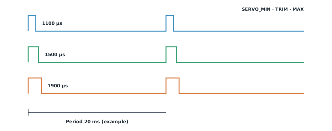
PWM servos and ESCs read the pulse width as the command. ArduPilot’s output defaults are SERVOx_MIN 1100, SERVOx_TRIM 1500 and SERVOx_MAX 1900 µs; the pulse frequency depends on the device, so check the documentation of the servo or ESC used.
Example 1 Finding PSC and ARR
Assume the timer clock is 84 MHz, we want to count in 1 µs steps, and a 20 ms period (an example).
f_tim = 84_000_000
tick_hz = 1_000_000                       # count in 1 µs steps
psc = f_tim // tick_hz - 1
period_us = 20_000
arr = period_us - 1
f_pwm = f_tim / ((psc + 1) * (arr + 1))
print(f"PSC = {psc}, ARR = {arr}, f_PWM = {f_pwm:.1f} Hz")
for pulse_us in (1100, 1500, 1900):
    print(f"pulse {pulse_us} µs -> CCR = {pulse_us}, duty = {pulse_us / (arr + 1):.2%}")
PSC = 83, ARR = 19999, f_PWM = 50.0 Hz
pulse 1100 µs -> CCR = 1100, duty = 5.50%
pulse 1500 µs -> CCR = 1500, duty = 7.50%
pulse 1900 µs -> CCR = 1900, duty = 9.50%With the timer counting in 1 µs steps, CCR equals the pulse width in microseconds, which keeps code readable. With a different clock, recalculate PSC, and ARR must not exceed the counter size (such as 65,535 for a 16-bit timer).
Polling and interrupts
- Polling: the main program checks the status repeatedly. Simple, but it wastes CPU and can miss short events
- Interrupts: the hardware pauses the main program to call an ISR (interrupt service routine), then resumes. The ISR must be as short as possible: set a flag and let the main program do the heavy work
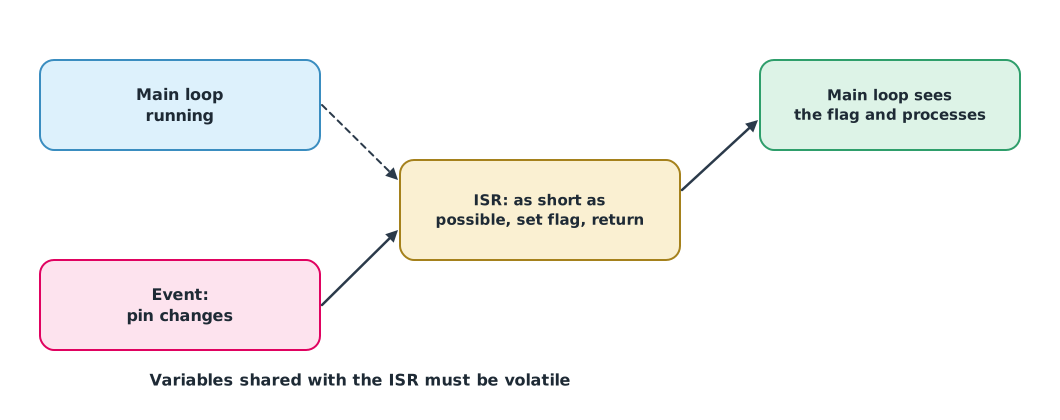
Mechanical buttons have contacts that bounce briefly when pressed, appearing as several presses. They must be debounced, accepting a new value only once it has been stable long enough.
Example 2 Debouncing a button
Read the pin every 1 ms (1 = released, with a pull-up) and accept a new value once stable for 5 ms.
samples = [1] * 5 + [0, 1, 0, 1, 1, 0, 0, 1, 0] + [0] * 20 + [1, 0, 1] + [1] * 15
raw_presses = sum(1 for a, b in zip(samples, samples[1:]) if a == 1 and b == 0)

stable, candidate, count, presses = 1, 1, 0, 0
for s in samples:
    count = count + 1 if s == candidate else 1
    candidate = s
    if count >= 5 and candidate != stable:
        stable = candidate
        presses += stable == 0
print(f"raw falling edges: {raw_presses}, debounced presses: {presses}")
raw falling edges: 5, debounced presses: 1One real press with bouncing contacts shows several falling edges; after debouncing there is one. The 5 ms is an example value; choose it from the characteristics of the button used.
Module lab
Lab: driving a servo and reading a button with interrupts
- Connect a button to a GPIO pin with the internal pull-up, read it by polling, and count presses without debouncing.
- Switch to an interrupt that sets a
volatileflag and debounce in the main loop, comparing the count with step 1. - Use the Pico 2 PWM to generate 1100, 1500 and 1900 µs pulses at the frequency given in the servo’s documentation, and measure them with an oscilloscope or logic analyzer.
- Connect a servo (separate power, common ground) and command it with all three pulses.
- Calculate PSC and ARR for the Pico 2 clock using the same approach as Example 1.
Common mistakes
Watch out
- Leaving inputs floating without a pull-up or pull-down
- Setting ARR beyond the counter size
- Doing heavy work in an ISR, such as printing or waiting
- Not debouncing buttons
- Powering a servo from the MCU’s supply pin until the supply sags
Summary
- GPIO inputs need a pull-up or pull-down
- PWM frequency is , and CCR sets the pulse width
- ArduPilot’s default pulses are 1100–1900 µs with 1500 µs centre
- Interrupts respond to events at once; ISRs must be short, and buttons must be debounced
Check your understanding
- With MHz, PSC = 47 and ARR = 999, what is the PWM frequency?
- In question 1, what is the duty cycle if CCR = 250?
- To count in 1 µs steps from a 150 MHz clock, what PSC is needed?
- What is ArduPilot’s default centre pulse (
SERVOx_TRIM)? - Why should an ISR be as short as possible?
Answers
- Hz
- 1500 µs
- While in the ISR, other work and same-level interrupts must wait; too long and the system misses its timing
Key formulas
| Timer PWM frequency | |
| Duty cycle |
Key references
- STMicroelectronics. General-purpose timer cookbook for STM32 microcontrollers (AN4776). link
- Raspberry Pi Ltd. RP2350 datasheet. link
- White, E. (2024). Making embedded systems: Design patterns for great software (2nd ed.). O'Reilly Media.
- ArduPilot Dev Team. ESC calibration. ArduPilot Copter documentation. link
Further reading
Study the assigned knowledge units in advance, review media and take the module quiz
In class / field
Lab or field practice from worksheets with a safety checklist
Learning evidence: Checked worksheets and quiz results