Serial interfaces and DroneCAN
UAT 204 Microcontrollers and Embedded Systems
Lesson
By the end of this module you will be able to
- Explain the 8N1 UART frame and calculate real throughput from baud rate
- Explain the I2C bus (addresses, pull-ups, speeds) and SPI (four CPOL/CPHA modes) and choose between them
- Explain CAN and DroneCAN and why they are used for multiple devices on a drone
- Design a simple data frame with a checksum and detect corrupted data
Why this matters
A flight controller talks to dozens of devices at once: the IMU sends thousands of readings a second over SPI, the compass and barometer use I2C, the GPS and telemetry radio use UART, and on larger drones the GPS, ESCs and power module share a single CAN bus. Choosing the wrong interface or speed makes data slow, lost or unanswered.
UART
A UART sends data one bit at a time on one wire per direction (TX crossed to RX), and both sides must use the same baud rate. Per Microchip TB3216, an 8N1 frame has one start bit, eight data bits and one stop bit, 10 bits per byte, so it carries baud/10 bytes per second.
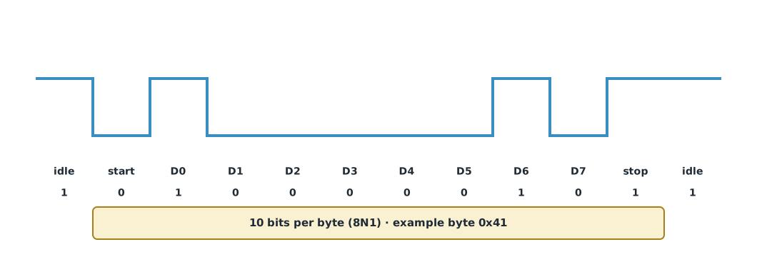
ArduPilot’s default baud rate is 57600 for telemetry ports and 230400 for the GPS port.
I2C and SPI
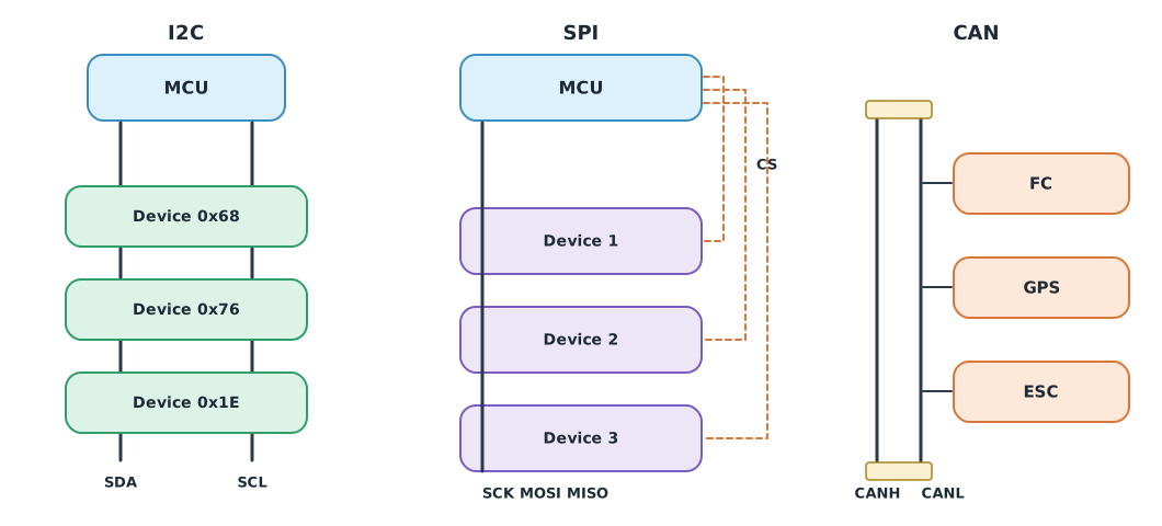
Under NXP’s I2C specification (UM10204 rev 7.0), the I2C bus uses two lines, SDA and SCL, which are open-drain and need pull-up resistors. Each device has a 7-bit address; standard speeds are 100 kbit/s (Standard-mode), 400 kbit/s (Fast-mode) and 1 Mbit/s (Fast-mode Plus). Many devices can share two wires, but it is slower than SPI.
SPI uses a clock (SCK), data lines MOSI and MISO, and a separate chip-select (CS) line for each device. It is much faster than I2C, so it is used for IMUs read frequently. Per Analog Devices, SPI has four modes set by clock polarity (CPOL) and the sampling edge (CPHA); both sides must use the same mode.
CAN and DroneCAN
CAN uses a CANH/CANL pair carrying a differential signal, so it resists noise and supports long runs. All devices connect to the same pair, with terminating resistors at both ends. The standard is ISO 11898-1 (latest edition 2024, which adds CAN XL). ArduPilot’s documentation says 1 Mbit/s is usually used, and CAN_P1_BITRATE defaults to 1,000,000.
DroneCAN is a protocol on CAN for unmanned aircraft, continuing UAVCAN v0. ArduPilot and PX4 support DroneCAN devices such as GPS units, compasses, ESCs and power modules. Advantages are less wiring and devices that report their own status.
Example 1 Real throughput
for label, baud in (("telemetry", 57_600), ("GPS", 230_400)):
    bytes_per_s = baud / 10                       # 8N1 = 10 bits per byte
    print(f"{label:<9} {baud:>7} baud -> {bytes_per_s:,.0f} bytes/s; a 40-byte message at 50 Hz uses "
          f"{40 * 50 / bytes_per_s:.0%} of the link")

bits = 9 * (1 + 1 + 1 + 6) + 2                    # address, register, repeated address, 6 data bytes + start/stop, approx.
for label, hz in (("I2C 100k", 100_000), ("I2C 400k", 400_000)):
    print(f"{label}: reading 6 bytes takes about {bits / hz * 1e6:.0f} µs")
telemetry 57600 baud -> 5,760 bytes/s; a 40-byte message at 50 Hz uses 35% of the link
GPS 230400 baud -> 23,040 bytes/s; a 40-byte message at 50 Hz uses 9% of the link
I2C 100k: reading 6 bytes takes about 830 µs
I2C 400k: reading 6 bytes takes about 208 µsA 40-byte message 50 times a second uses about a third of a 57600 telemetry link, so adding other messages may exceed capacity. Reading 6 sensor bytes over I2C at 400 kHz takes about 0.2 ms, allowing hundreds of reads a second with few devices. The I2C bit count in the example is an approximation.
Detecting corruption with a checksum
Example 2 A simple frame with a checksum
Our sensor module sends a hypothetical frame: start byte 0xAA, length, data, and an XOR checksum of the length and data bytes.
def make_frame(payload):
    body = bytes([len(payload)]) + payload
    checksum = 0
    for b in body:
        checksum ^= b
    return bytes([0xAA]) + body + bytes([checksum])


def check_frame(frame):
    if frame[0] != 0xAA or frame[1] != len(frame) - 3:
        return False
    checksum = 0
    for b in frame[1:-1]:
        checksum ^= b
    return checksum == frame[-1]


frame = make_frame(bytes([0x09, 0xC4, 0x01, 0x2C]))       # e.g. voltage 2500 and temperature 300
print("frame:", frame.hex(" "), "| valid:", check_frame(frame))
damaged = bytearray(frame); damaged[3] ^= 0x10              # noise flips one bit
print("damaged:", bytes(damaged).hex(" "), "| valid:", check_frame(bytes(damaged)))
frame: aa 04 09 c4 01 2c e4 | valid: True
damaged: aa 04 09 d4 01 2c e4 | valid: FalseAn XOR checksum catches a single flipped bit but misses some damage, such as the same bit position flipping in two bytes. Real protocols such as MAVLink and DroneCAN therefore use stronger CRCs.
Module lab
Lab: connecting a sensor and sending data to the flight controller
- Connect an I2C sensor (such as the barometer or IMU on the training board) to the Pico 2, scan the bus for device addresses and read values.
- Capture SDA and SCL with a logic analyzer, identifying start, address, ACK and data.
- Send frames as in Example 2 over UART to a computer, and write a receiver that checks the checksum.
- Set a wrong baud rate on one side, observe the data received and explain why.
- Study ArduPilot’s DroneCAN page and identify the parameters needed to use a DroneCAN GPS.
Common mistakes
Watch out
- Wiring TX to TX instead of crossing to RX
- Forgetting I2C pull-ups, or paralleling several sets until they are too strong
- Duplicate I2C addresses on one bus
- Setting an SPI mode that does not match the device
- Not terminating the CAN bus, or terminating it incorrectly
Summary
- An 8N1 UART uses 10 bits per byte, carrying baud/10 bytes per second
- I2C uses two addressed wires with pull-ups; SPI is faster but needs a separate CS per device
- CAN resists noise with many devices on one pair; DroneCAN is the drone protocol on CAN
- Transmitted data should carry a checksum or CRC to detect corruption
Check your understanding
- How many bytes per second does a 115200 baud 8N1 UART carry?
- What is the I2C Fast-mode speed?
- How many CS lines does SPI need for three devices?
- Which protocol does DroneCAN continue?
- What is 0x0F XOR 0xF0?
Answers
- bytes per second
- 400 kbit/s
- Three, one per device
- UAVCAN v0
- 0xFF
Key formulas
| UART 8N1 throughput | |
| XOR checksum |
Key references
- Microchip Technology. (2018). Getting started with USART (TB3216). link
- NXP Semiconductors. (2021). I2C-bus specification and user manual (UM10204, Rev. 7.0). link
- Dhaker, P. (2018). Introduction to SPI interface. Analog Dialogue, 52(3). link
- International Organization for Standardization. (2024). Road vehicles — Controller area network (CAN) — Part 1: Data link layer and physical coding sublayer (ISO 11898-1:2024). link
- DroneCAN Development Team. DroneCAN: A lightweight protocol for UAV CAN networks. link
- ArduPilot Dev Team. CAN bus setup (advanced). ArduPilot Copter documentation. link
- ArduPilot Dev Team. DroneCAN setup (advanced). ArduPilot Copter documentation. link
Further reading
Study the assigned knowledge units in advance, review media and take the module quiz
Serial interfaces: UART, I2C, SPI, CAN and DroneCAN
Reading MAVLink telemetry from SITL
Drone communications and MAVLink
In class / field
Lab or field practice from worksheets with a safety checklist
Learning evidence: Checked worksheets and quiz results