Selecting and installing equipment
UAT 321 Unmanned Aircraft Systems Installation, Integration, Inspection and Maintenance Laboratory
Lesson
By the end of this module you will be able to
- Read a multirotor connection diagram and state the voltage, protocol and data direction of every line
- Build a mass budget, find the centre of gravity and calculate the thrust-to-weight ratio from propulsion test data
- Estimate energy and hover time with stated assumptions, and check the ESC current margin
- Install equipment for mechanical, electrical and data compatibility, and record the evidence
Why this matters
A drone built from good parts may still not fly if the parts do not fit together: connectors that look identical but have different pinouts, a propeller that draws more current than the ESC can handle, or an added camera that shifts the centre of gravity so one motor works hard all the time. A builder’s job therefore starts before the first bolt is tightened: calculate and plan so every part works with the others, then record it so others can check.
This module uses one hypothetical case throughout the course: a quadcopter for survey photography belonging to an agency, running a 6-cell battery with a camera mounted at the front.
The connection diagram
A connection diagram maps every wire in the aircraft: which lines carry power, which carry data, and which way the data flows. It is like the wiring plan an electrician needs before running cables in a house.
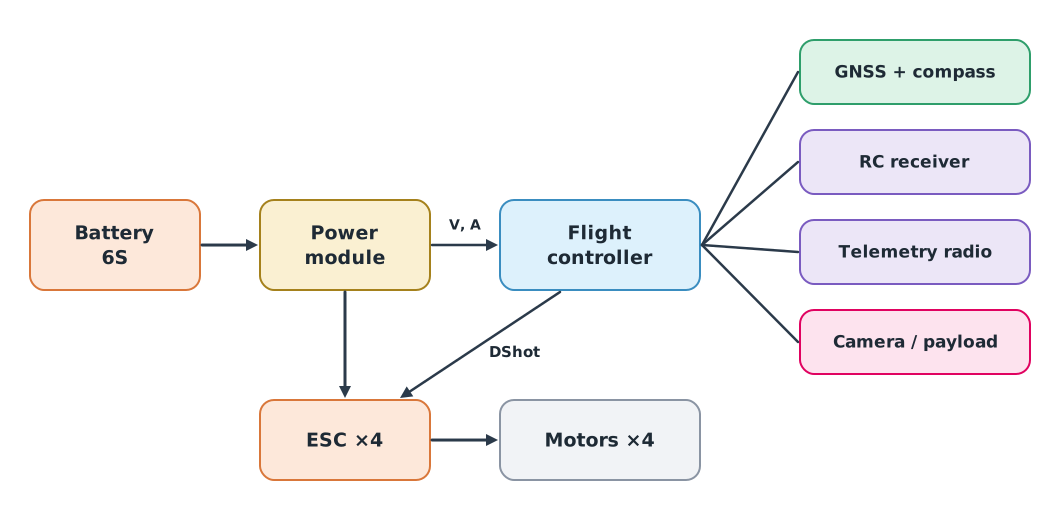
- Power flows from the battery through the power module to the ESCs and motors. These lines carry tens of amperes and need wires and connectors rated for that current
- Voltage and current data from the power module go to the flight controller, which uses them to estimate remaining energy and trigger failsafes
- Motor commands go from the flight controller to the ESCs. Modern ESCs commonly use the digital DShot protocol; the ArduPilot documentation recommends DShot600 for most boards. ESCs using DShot or the CAN bus (DroneCAN) do not need the throttle-range calibration that PWM ESCs need
- Peripherals such as the GNSS and compass, RC receiver, telemetry radio and camera each use different ports and protocols, such as UART, I2C or CAN
The connection register
Each line in the diagram should have one row in a register: source, destination, voltage, pinout, protocol, data rate and checker. Connectors that look the same do not guarantee matching voltages or pinouts. Compare against the manuals of both sides before every first connection.
Mass budget and centre of gravity
A mass budget lists the mass of every part, including those that are often forgotten: wires, connectors, mounts and straps. The centre of gravity (CG) is the point where the drone would balance on a fingertip. It is the average of each part’s position weighted by its mass, with every position measured from the same reference point (origin).
If the CG is not beneath the centre of the four motors, the motors nearer the CG must work harder to keep the aircraft level, leaving less reserve thrust and draining the battery faster. The FAA’s aviation maintenance technician handbook uses the same principle for aircraft weight and balance.
Example 1 Mass budget and CG
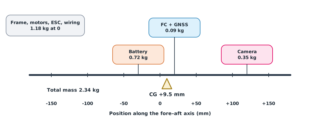
Positions are measured along the fore–aft axis from the frame centre, positive towards the nose. The 0.35 kg camera sits 120 mm forward.
parts = {  # name: (mass kg, position x m; positive = towards the nose)
    "frame": (0.62, 0.0), "motors": (0.34, 0.0), "ESCs": (0.10, 0.0), "FC + GNSS": (0.09, 0.02),
    "battery": (0.72, -0.03), "camera": (0.35, 0.12), "wiring and mounts": (0.12, 0.0),
}
mass = sum(m for m, _ in parts.values())
cg_x = sum(m * x for m, x in parts.values()) / mass
print(f"total mass {mass:.2f} kg, CG {cg_x * 1000:+.1f} mm from the frame centre")

others = sum(m * x for name, (m, x) in parts.items() if name != "battery")
battery_x = -others / parts["battery"][0]
print(f"move the battery to x = {battery_x * 1000:+.1f} mm to centre the CG")
total mass 2.34 kg, CG +9.5 mm from the frame centre
move the battery to x = -60.8 mm to centre the CGThe CG is 9.5 mm forward of centre because the heavy camera is at the front. A fix that adds no mass is to slide the battery aft from −30 to about −61 mm, but check that the battery tray allows it, the wires are not strained, and the frame manual’s CG limits accept it.
Thrust, current and energy
The thrust-to-weight ratio (TWR) is the total maximum thrust divided by the weight, both as forces in the same unit (newtons). Weight is not the same as mass . Thrust must come from the manufacturer’s test table for the motor, propeller and voltage actually used. A motor’s KV rating does not tell you its thrust: the same motor with different propellers gives different thrust and draws different current.
Example 2 TWR and ESC current margin
A hypothetical test table for the motor and propeller at 6S gives 14.0 N maximum thrust per motor at a maximum current of 22 A, and the ESCs are rated 30 A continuous.
g = 9.81
weight = mass * g
max_thrust_per_motor = 14.0   # N, from the test table for this motor, propeller and voltage
twr = 4 * max_thrust_per_motor / weight
hover_share = weight / 4 / max_thrust_per_motor
print(f"weight {weight:.2f} N, TWR {twr:.2f}, hover needs {hover_share:.0%} of max thrust per motor")

esc_rating, max_motor_current = 30, 22   # A
print(f"ESC current margin {(esc_rating - max_motor_current) / esc_rating:.0%}")
weight 22.96 N, TWR 2.44, hover needs 41% of max thrust per motor
ESC current margin 27%Hovering uses about 41% of each motor’s thrust, leaving reserve for climbing, wind and attitude corrections. The ESCs have a 27% current margin, but you must also check ESC cooling in its actual mounting position.
Battery energy is approximately the nominal voltage times the capacity; divide by average power to get time. This is a starting model, because voltage and power change with load, temperature and battery age.
v_nominal, capacity_ah = 22.2, 5.0          # 6S 5000 mAh
usable_wh = v_nominal * capacity_ah * 0.80  # assume 80% of nominal energy is usable
hover_power = 4 * 62                        # W, from the test table at hover thrust
print(f"nominal {v_nominal * capacity_ah:.0f} Wh, usable {usable_wh:.1f} Wh, "
      f"hover about {usable_wh / hover_power * 60:.1f} min")
nominal 111 Wh, usable 88.8 Wh, hover about 21.5 minThe 80% and 62 W per motor are assumptions of this example; do not apply them to another aircraft without checking. The time must be confirmed by a test flight whose voltage and current log you read, which you will do in module 2.
Installing for compatibility
Compatibility has three dimensions, and all three should be checked before first power-up.
| Dimension | What to check | Example mistake |
|---|---|---|
| Mechanical | Secure mounts, propeller clearance, flight-controller vibration isolation, board arrow direction | Flight controller mounted backwards without setting the board orientation |
| Electrical | Operating voltage, peak current, polarity, fuses or protection | A 12 V camera connected to a 5 V rail, or reversed polarity |
| Data | Port, protocol, baud rate, pinout, signal voltage level | TX wired to TX instead of crossing to RX |
The compass should be kept away from high-current wires and motors, because current creates interfering magnetic fields; this is why GNSS and compass units are often mounted on a mast. The flight controller should sit on a vibration-isolating mount that is not so loose it moves freely.
Bench safety
Remove all propellers before connecting a battery to configure or test motors. The ArduPilot documentation requires propellers to be removed before using motor test. Use a current-limited supply or a “smoke stopper” for the first power-up after soldering, and keep a sand bucket or fire-resistant container ready for lithium batteries.
Module lab
Lab: assemble and document the training drone
- Draw the connection diagram of the lab’s training drone and build a register row for every line (source, destination, voltage, pinout, protocol, checker).
- Weigh every part on a digital scale, measure positions from one origin, and calculate the CG with the code in Example 1. Compare with the real balance point found by hanging or fingertip balancing.
- Find the test table for the actual motor and propeller, and calculate TWR, current margin and approximate hover time, citing the source of every number.
- Install the flight controller, GNSS and receiver, checking all three compatibility dimensions. Photograph mounts and connectors as evidence.
- Power up for the first time through a current limiter with no propellers fitted, and record the results in the lab notebook for the instructor to sign.
Common mistakes
Watch out
- Leaving wires, connectors and mounts out of the mass budget, so the real mass exceeds the calculation
- Measuring positions from different origins, giving a wrong CG
- Using KV instead of thrust data, or a test table for a different voltage or propeller
- Converting mAh straight to time without going through energy and power
- Assuming a connector that fits is wired correctly without comparing pinouts
- Testing motors with propellers fitted
Summary
- The connection diagram and register show power, data and protocol for every line
- The mass budget must include every part; CG is the sum of divided by total mass, from one origin
- TWR uses thrust from a test table matching the real set-up, and the ESC current margin must be checked
- Flight time from energy divided by power is a starting model to be confirmed from logs
- Check mechanical, electrical and data compatibility, and always remove propellers for bench tests
Check your understanding
- A 2 kg part is at and a 0.5 kg part at m. Where is the CG?
- A 2.0 kg drone has 49.05 N of total maximum thrust. What is its TWR (use )?
- What is the nominal energy of a 4S (14.8 V) 5200 mAh battery in Wh?
- With 88.8 Wh usable and 400 W average power, about how many minutes can it fly?
- Why must propellers be removed before bench-testing motors?
Answers
- m, or 40 mm towards the 0.5 kg part
- Wh
- minutes
- Motors may spin unexpectedly or in the wrong direction; a spinning propeller on a bench can cause serious injury, and the firmware documentation requires removing them before testing
Key formulas
| Centre of gravity along one axis | |
| Thrust-to-weight ratio | |
| Approximate energy and flight time |
Key references
- ArduPilot Dev Team. ArduPilot documentation. link
- ArduPilot Dev Team. Connect ESCs and motors (motor test). ArduPilot Copter documentation. link
- ArduPilot Dev Team. DShot and bi-directional DShot. ArduPilot Copter documentation. link
- DroneCAN Development Team. DroneCAN: A lightweight protocol for UAV CAN networks. link
- Federal Aviation Administration. (2023). Aviation maintenance technician handbook – General (FAA-H-8083-30B). link
- ASTM International. (2019). Standard specification for continued airworthiness of lightweight unmanned aircraft systems (ASTM F2909-19). link
Further reading
Study the assigned knowledge units in advance, review media and take the module quiz
Designing and integrating drone systems
PX4 and ArduPilot architecture
In class / field
Intensive lab and field practice recorded in a lab notebook
Learning evidence: Lab notebook signed by the instructor