Calibration and testing
UAT 321 Unmanned Aircraft Systems Installation, Integration, Inspection and Maintenance Laboratory
Lesson
By the end of this module you will be able to
- Order the calibration of sensors, radio, ESCs and battery monitoring before first flight, with the reason for each step
- Adjust the power module's voltage and current multipliers from reference measurements
- Analyse a vibration log against ArduPilot's guidance and decide whether action is needed
- Configure the battery failsafe and explain the role of pre-arm checks
Why this matters
A flight controller knows the world only through its sensors. If the accelerometer believes level is tilted by 3°, the drone drifts one way all the time. If the compass is disturbed, the drone may circle in a growing spiral (“toilet bowling”). And if the battery monitor reads the voltage wrongly, the failsafe triggers too late and the battery runs out in the air. Calibration teaches every sensor to read the truth; a test flight and its log provide the evidence that it worked.
The calibration sequence
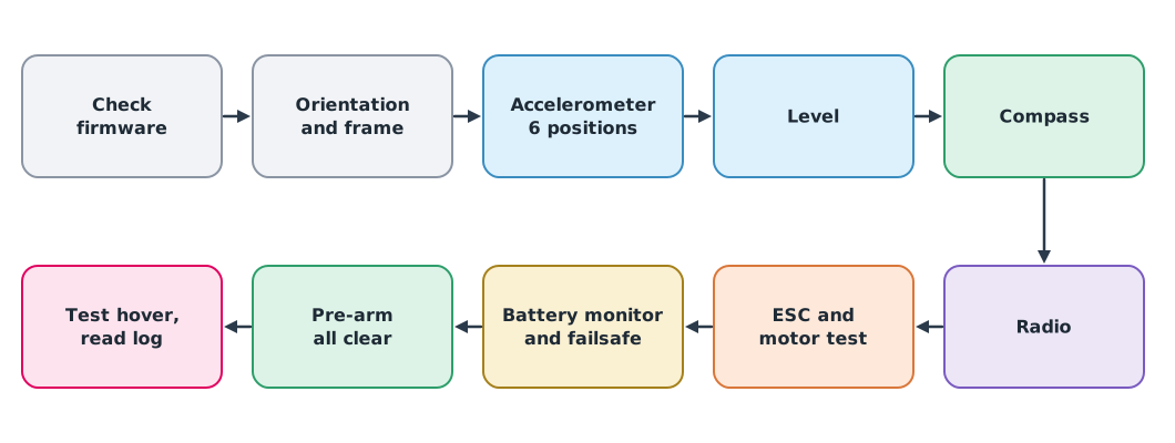
The order matters, because later steps depend on earlier ones. If the board orientation is wrong, for example, the whole accelerometer calibration will be wrong too.
- Firmware version and frame type: always record the version, because parameter names and procedures change between versions
- Board orientation: tells the system which way the board faces relative to the airframe
- Accelerometer, six positions: hold the aircraft still in six attitudes (level, left side, right side, nose down, nose up and upside down) to find each axis’s offset and scale
- Level: defines the aircraft’s level attitude. The ArduPilot documentation notes it can compensate for a board mounted up to about 10° off level
- Compass: rotate the aircraft through every direction, outdoors and away from steel structures and cars. Recalibrate after installing new equipment near the compass
- Radio: tells the system the end points and centre of each channel
- ESCs and motor test: PWM ESCs need throttle-range calibration; DShot and DroneCAN ESCs do not. Then run motor test one motor at a time with the propellers removed to confirm order and direction against the frame’s motor map
- Battery monitor and failsafe (next sections)
- Pre-arm: the system checks itself before allowing arming. All checks must pass; do not disable checks just to be able to fly
PX4 uses a similar standard sequence through QGroundControl: sensor orientation, compass, gyroscope, accelerometer and level horizon.
Calibrating the battery monitor
The power module reports voltage and current through multipliers in the parameters. If a multiplier is wrong, every decision based on voltage or remaining energy is wrong too. To check, measure the real voltage with a multimeter, and compare the charge used according to the log with the charge the charger puts back.
Example 1 Adjusting the voltage and current multipliers
old_volt_mult = 10.10
reported_v, meter_v = 22.05, 22.41      # system reading and multimeter reading, taken together
new_volt_mult = old_volt_mult * meter_v / reported_v
print(f"new voltage multiplier {new_volt_mult:.3f}")

logged_mah, charger_mah = 3620, 3980    # charge used according to the log, and charge put back by the charger
print(f"current reading low by {1 - logged_mah / charger_mah:.1%}; scale current by {charger_mah / logged_mah:.3f}")
new voltage multiplier 10.265
current reading low by 9.0%; scale current by 1.099The system under-reads current by 9%, so it believes more energy remains than really does. The charger usually puts back slightly more than was used because charging has losses, so compare several flights before adjusting.
Battery failsafe
A failsafe is an automatic action when something goes wrong, such as returning home or landing when the battery is low.
- ArduPilot has two levels, low and critical, each settable by voltage and by remaining charge. The default low voltage is 10.5 V, which suits a 3-cell battery, so a 6-cell battery must be configured. By default the failsafe triggers only when voltage stays below the threshold for 10 seconds, so a momentary sag during a climb does not trigger it falsely, and the action can be chosen, for example land or return
- PX4 estimates remaining charge from voltage per cell, treating 3.6 V per cell under load as “empty” and 4.05 V as “full” by default, with thresholds of 15% for low, 7% for critical and 5% for emergency
Suitable values depend on the battery, the mission and the distance home. Set them from testing and record the reasons; do not accept defaults unchecked.
Testing vibration from the log
Excessive vibration corrupts accelerometer readings, and the position estimator may compute the wrong altitude, even making the drone climb on its own. ArduPilot logs a VIBE message with the vibration level of each axis (m/s²) and a cumulative count of how many times an accelerometer hit the limit of its measuring range (clipping).
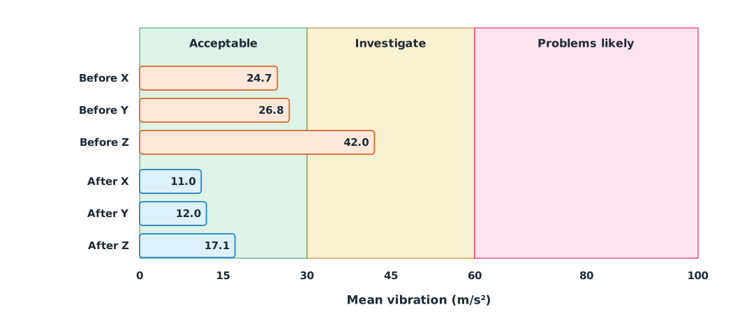
The ArduPilot documentation says levels below 30 m/s² are normally acceptable, levels above 60 m/s² nearly always cause problems, and clipping should be zero (increases only during hard landings may not be a problem). PX4 does not give numeric thresholds like these but recommends inspecting the vibration plots in Flight Review.
Example 2 Vibration before and after replacing a propeller
The file vibe_log.csv holds synthetic VIBE-style data from two 2-minute hovers, before and after replacing a chipped propeller; it is not a log from any real aircraft. The data files, the script that generates them and the lesson code are at /downloads/uat-321/.
import pandas as pd

vibe = pd.read_csv("vibe_log.csv")
axes = ["VibeX", "VibeY", "VibeZ"]
for flight, g in vibe.groupby("flight", sort=False):
    worst = g[axes].max(axis=1)
    new_clips = g["Clip"].iloc[-1] - g["Clip"].iloc[0]
    means = ", ".join(f"{a[-1]} {g[a].mean():.1f}" for a in axes)
    print(f"{flight:<7} mean {means} | over 30: {(worst > 30).mean():.0%}, "
          f"over 60: {(worst > 60).mean():.1%}, new clips {new_clips}")
before mean X 24.7, Y 26.8, Z 42.0 | over 30: 99%, over 60: 2.8%, new clips 17
after mean X 11.0, Y 12.0, Z 17.1 | over 30: 0%, over 60: 0.0%, new clips 0Before the fix, the Z axis averages 42 m/s², in the range that needs investigating, with spells above 60 and 17 new clipping events. After the new propeller, every axis is below 30 with no new clipping, which is evidence the fix worked. If vibration remained, the next checks would be propeller balance, motor bearings, arm stiffness and the isolation mount.
Module lab
Lab: calibration and first test flight
- Calibrate in the order of Figure 1 using Mission Planner or QGroundControl, recording the firmware version and a screenshot of each result.
- With propellers removed, test each motor and confirm order and direction against the frame’s motor map.
- Measure voltage with a multimeter, adjust the voltage multiplier, and set 6-cell battery failsafe thresholds with reasons.
- Under the instructor’s supervision, hover for 2 minutes in an enclosed area, download the log, and analyse vibration with the code in Example 2.
- Compare the charge used in the log with the charge put back by the charger, and decide whether the current multiplier needs adjusting.
Common mistakes
Watch out
- Calibrating the compass indoors or near steel, so the offsets are wrong from the start
- Setting board orientation after accelerometer calibration, which then has to be repeated
- Using 3-cell failsafe defaults on a 6-cell battery
- Disabling pre-arm checks to be able to arm instead of fixing the cause
- Looking only at mean vibration without checking time above the limits and clipping
Summary
- Calibrate in order, because later steps depend on earlier ones, and always record the firmware version
- PWM ESCs need range calibration; DShot and DroneCAN do not. Always remove propellers for motor tests
- The voltage multiplier is adjusted by the ratio of meter reading to system reading
- ArduPilot’s vibration guidance: below 30 m/s² acceptable, above 60 m/s² problems likely, and clipping should be zero
- The battery failsafe must match the cell count and the mission
Check your understanding
- The voltage multiplier is 10.0, the system reads 20.0 V and a meter reads 20.5 V. What is the new multiplier?
- Mean Z-axis vibration is 45 m/s². Which range is that in, by ArduPilot’s guidance?
- Which kinds of ESC do not need throttle-range calibration?
- Why does the low-voltage failsafe wait for voltage to stay low for a while before acting?
- The log shows 3000 mAh used but the charger puts back 3300 mAh. By about what percentage does the system under-read current?
Answers
- The 30–60 m/s² range: investigate the cause
- DShot and DroneCAN ESCs
- So a momentary sag during high current draw, such as a climb, does not trigger the failsafe falsely
Key formulas
| Adjusting the voltage multiplier | |
| Fraction of time above a limit |
Key references
- ArduPilot Dev Team. Accelerometer calibration. ArduPilot Copter documentation. link
- ArduPilot Dev Team. Compass calibration. ArduPilot Copter documentation. link
- ArduPilot Dev Team. ESC calibration. ArduPilot Copter documentation. link
- ArduPilot Dev Team. Connect ESCs and motors (motor test). ArduPilot Copter documentation. link
- ArduPilot Dev Team. Measuring vibration. ArduPilot Copter documentation. link
- ArduPilot Dev Team. Pre-arm safety checks. ArduPilot Copter documentation. link
- ArduPilot Dev Team. Battery failsafe. ArduPilot Copter documentation. link
- PX4 Autopilot. Standard configuration (sensor calibration). PX4 user guide. link
- PX4 Autopilot. Battery estimation tuning. PX4 user guide. link
Further reading
Study the assigned knowledge units in advance, review media and take the module quiz
Calibration and measurement uncertainty
UAV testing and evidence analysis
In class / field
Intensive lab and field practice recorded in a lab notebook
Learning evidence: Lab notebook signed by the instructor