Survey planning
UAT 361 Unmanned Aircraft Systems Technology for Surveying, Mapping and Inspection
Lesson
By the end of this module you will be able to
- Write a survey brief that states the user, deliverables, coordinate system and acceptance criteria before planning the flight
- Compute GSD and ground footprint from camera data and flight height
- Compute photo spacing, flight-line spacing, photo count and flight time from overlap settings
- Explain how terrain affects GSD and overlap, and choose a flight pattern suited to the site
Why this matters
A drone map can be no better than the images behind it. Fly too high and the detail you need is smaller than a pixel. Overlap too little and the software cannot join the images. Fail to agree the coordinate system at the start and the user may open the file to find the map hundreds of metres out of place. None of these can be fixed in the office; the site has to be flown again. Planning is therefore the most valuable step of any survey.
The whole course follows one hypothetical case: surveying a 240 × 160 m materials yard in an industrial estate to measure the yard area and stockpile volumes, and inspecting the solar roof of the building next door. All numbers are synthetic training data, not real survey results. The Python code for every module can be downloaded from /downloads/uat-361/.
Start from the brief, not the flight height
A survey brief is a one-page agreement made before any calculation. It answers six questions.
| Item | Question | Example in our case |
|---|---|---|
| Use | Who will decide what with it? | The stores team needs the yard area and stockpile volumes every month |
| Extent | Which area, and when? | The 240 × 160 m yard, in the morning when loaders are idle |
| Deliverables | Which file types? | Orthomosaic (GeoTIFF), DSM and a volume report |
| Reference system | Which coordinates, units and heights? | WGS 84 / UTM zone 47N (EPSG:32647), metres, orthometric heights |
| Criteria | How will it be accepted? | Accuracy at checkpoints and completeness of the area (module 5) |
| Limits | What cannot be seen or reached? | No imagery under the storage shed roof; must be stated in the report |
Thailand lies in UTM zones 47N and 48N (EPSG:32647 and 32648) on WGS 84. Older data may use the Indian 1975 datum, whose coordinates can differ by hundreds of metres. Never guess the EPSG code; ask the user which system their existing data uses. If the user has not set an accuracy requirement, record it as “to be confirmed” rather than promising one from the camera resolution.
GSD and ground footprint
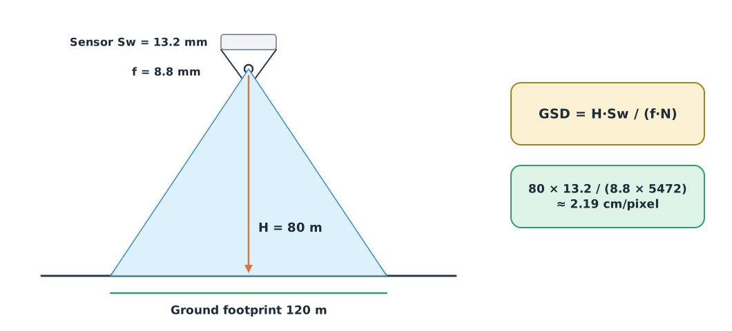
GSD (ground sampling distance) is the size of ground covered by one pixel, like the grain size of the picture. With a 2 cm GSD, objects smaller than 2 cm cannot be resolved as separate detail. For a camera looking straight down on flat ground:
where is the camera height above the ground (m), the sensor width (mm), the real focal length (mm) and the number of pixels across the width. The ground width is the footprint. Pix4D stresses that the real focal length must be used, not the 35 mm equivalent.
GSD is not coordinate accuracy
A 2 cm GSD tells you the size of detail you can see. It does not guarantee that positions on the map are within 2 cm. Accuracy must be proven with independent checkpoints in module 5.
Overlap and flight lines
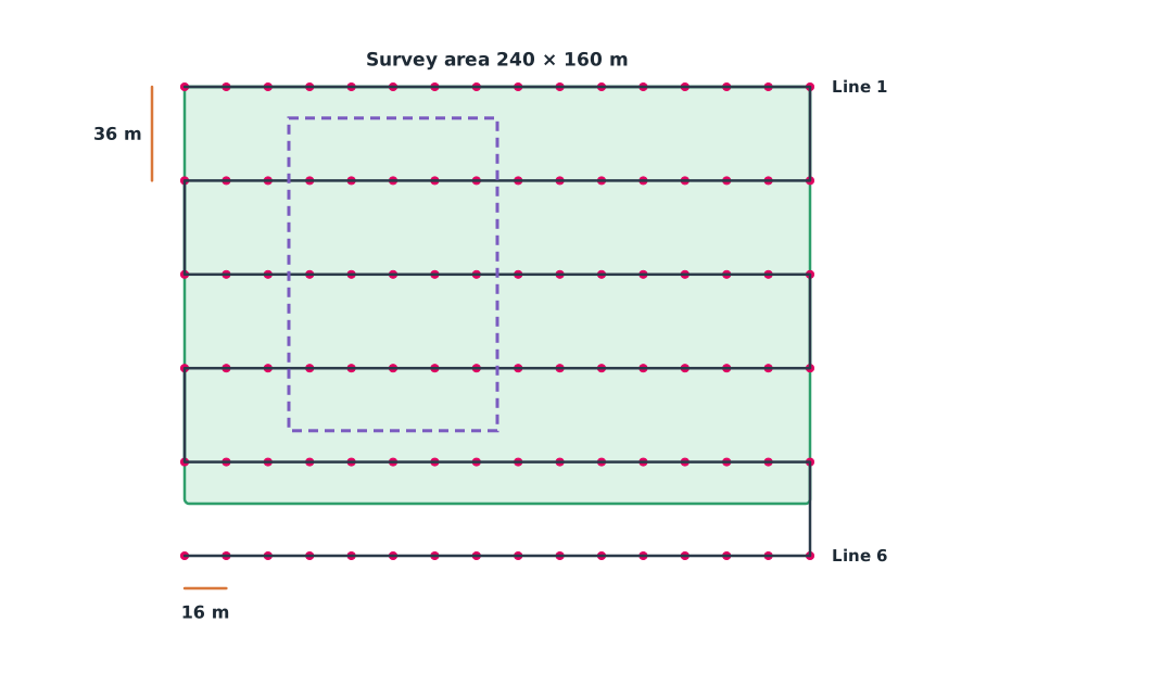
Mapping software must see the same point in several images, so images must overlap in two directions. Front overlap () is the overlap between consecutive images along a line; side overlap () is the overlap between images on neighbouring lines.
is the distance between photo stations and the distance between flight lines. Planning software such as QGroundControl (Survey pattern) computes these once you choose a camera and overlaps, but the engineer must be able to check that the numbers make sense.
Example 1. Comparing plans at three heights
Assumed camera: 13.2 × 8.8 mm sensor, 5472 × 3648 pixels, = 8.8 mm, with the long side of the image across track, 80/70% overlap and 5 m/s ground speed.
import math

SENSOR_W, SENSOR_H, FOCAL, PX_W = 13.2, 8.8, 8.8, 5472    # mm, mm, mm, pixels
AREA_ALONG, AREA_ACROSS = 240, 160                        # m
FRONT, SIDE, SPEED = 0.80, 0.70, 5.0

for h in (60, 80, 100):
    gsd_cm = h * SENSOR_W / (FOCAL * PX_W) * 100
    across, along = h * SENSOR_W / FOCAL, h * SENSOR_H / FOCAL
    base, spacing = along * (1 - FRONT), across * (1 - SIDE)
    lines = math.ceil(AREA_ACROSS / spacing) + 1
    per_line = math.floor(AREA_ALONG / base) + 1
    path_m = lines * AREA_ALONG + (lines - 1) * spacing
    print(f"H {h:>3} m: GSD {gsd_cm:.2f} cm, footprint {across:.0f} x {along:.0f} m, "
          f"base {base:.0f} m, spacing {spacing:.0f} m, {lines} lines x {per_line} = {lines * per_line} photos, "
          f"{path_m / SPEED / 60:.1f} min, trigger every {base / SPEED:.1f} s")
H 60 m: GSD 1.64 cm, footprint 90 x 60 m, base 12 m, spacing 27 m, 7 lines x 21 = 147 photos, 6.1 min, trigger every 2.4 s
H 80 m: GSD 2.19 cm, footprint 120 x 80 m, base 16 m, spacing 36 m, 6 lines x 16 = 96 photos, 5.4 min, trigger every 3.2 s
H 100 m: GSD 2.74 cm, footprint 150 x 100 m, base 20 m, spacing 45 m, 5 lines x 13 = 65 photos, 4.6 min, trigger every 4.0 sAt 80 m the GSD is about 2.2 cm with 6 lines and 96 photos. Dropping to 60 m improves detail but increases the number of photos by about half (147 photos), and the camera must fire every 2.4 s, so check that it can record that fast. The time excludes take-off, landing, turns and wind. One extra line is added so the edges of the area have enough overlap.
Terrain and flight patterns
The height in the formula is the height above the ground being imaged, not above the take-off point. If the ground rises 20 m while the drone stays at 80 m, the real height is 60 m and the footprint shrinks to 90 × 60 m, yet the photo spacing is still 16 m and the line spacing still 36 m, so overlap falls.
Example 2. Overlap when the ground rises
SENSOR_W, SENSOR_H, FOCAL = 13.2, 8.8, 8.8
BASE, SPACING = 16, 36                  # planned at 80 m above flat ground
for ground_rise in (0, 10, 20, 30):
    h = 80 - ground_rise
    across, along = h * SENSOR_W / FOCAL, h * SENSOR_H / FOCAL
    front, side = 1 - BASE / along, 1 - SPACING / across
    print(f"ground +{ground_rise:>2} m -> height {h} m: front {front:.0%}, side {side:.0%}")
ground + 0 m -> height 80 m: front 80%, side 70%
ground +10 m -> height 70 m: front 77%, side 66%
ground +20 m -> height 60 m: front 73%, side 60%
ground +30 m -> height 50 m: front 68%, side 52%When the ground rises 30 m, side overlap falls from 70% to 52% and front overlap to 68%, and that part of the site may not join. The remedy is terrain following, which adjusts height from a terrain model, or planning with extra overlap. QGroundControl warns that flat-ground calculations do not hold when the ground differs greatly from the take-off point, and a terrain model does not know where every power line or tree is.
Choose the flight pattern to suit the site:
- Survey (grid) for polygon areas such as our yard
- Corridor scan for long, narrow areas such as roads, canals or power lines, defined by a centre line and a width
- Oblique images or crossing lines in two directions when building sides must be seen or a better 3D model is needed, at the cost of more time and more images
Before flying, check the CAAT requirements for registration, permission, restricted areas and height (see UAT 313), and obtain the landowner’s permission. The numbers in this module show geometry; they are not authorised flight levels.
Module lab
Lab: a brief and two flight plans
- Write a one-page brief for the training site set by the instructor, covering all six items in the table and listing what is “to be confirmed”
- Using the real camera data of the lab drone, run Example 1 for two heights and choose a plan with reasons
- Build a Survey plan in QGroundControl offline and compare its photo spacing, line spacing and photo count with the code; explain any differences
- Apply Example 2 to the height range of the training site and decide whether terrain following is needed
- Check the flight requirements for the site and record everything in the lab notebook for the instructor to sign
Common mistakes
Watch out
- Using the 35 mm equivalent focal length instead of the real one, which makes the whole GSD wrong
- Setting height above take-off and assuming it is the same above the ground everywhere
- Flying lower for more detail without checking that the camera can keep up
- Fitting the flight lines exactly to the survey boundary, leaving the edges without enough overlap
- Guessing the EPSG code or delivering without stating the height system
Summary
- Start from the brief: user, deliverables, coordinate system, criteria and limits, before computing the plan
- GSD = H·Sw/(f·N) describes the size of detail, not coordinate accuracy
- Photo spacing and line spacing come from the footprint multiplied by (1 − overlap)
- Rising terrain reduces the real height and the overlap, so choose the pattern and height accordingly
Check your understanding
- A camera with = 13.2 mm, = 8.8 mm and 5472 pixels flies at 100 m. What is the GSD?
- The along-track footprint is 80 m with 75% front overlap. What is the photo spacing?
- The across-track footprint is 120 m with 60% side overlap. What is the line spacing?
- With a 16 m photo spacing at 8 m/s, how often must the camera fire?
- Why does hilly terrain need terrain following or extra overlap?
Answers
- m ≈ 2.74 cm/pixel
- m
- m
- s
- Higher ground reduces the height above the ground, narrows the footprint and reduces overlap until the images may not join
Key formulas
| Ground sampling distance | |
| Ground footprint | |
| Photo spacing and line spacing |
Key references
- Pix4D. Computing the flight height for a given GSD [Support article]. Pix4D SA. link
- QGroundControl Dev Team. Survey (plan pattern). QGroundControl user guide. link
- QGroundControl Dev Team. Corridor scan (plan pattern). QGroundControl user guide. link
- IOGP. WGS 84 / UTM zone 47N (EPSG:32647). EPSG geodetic parameter dataset. link
- Wolf, P. R., DeWitt, B. A., & Wilkinson, B. E. (2014). Elements of photogrammetry with applications in GIS (4th ed.). McGraw-Hill Education. link
- Sampath, A., Shrestha, M., While, M., & Scholl, V. M. (2023). Guidelines for calibration of uncrewed aircraft systems imagery (Open-File Report 2023–1033). U.S. Geological Survey. link
- สำนักงานการบินพลเรือนแห่งประเทศไทย. (2569). ประกาศ กพท. เรื่อง หลักเกณฑ์และวิธีการในการอนุญาตให้ผู้บังคับหรือปล่อยอากาศยานซึ่งไม่มีนักบิน ประเภทอากาศยานที่ควบคุมการบินจากภายนอก ที่มีน้ำหนักไม่เกิน 25 กิโลกรัม ปฏิบัติแตกต่างไปจากเงื่อนไขที่กำหนด พ.ศ. 2569 (มีผล 17 พฤษภาคม 2569). link
Further reading
Study the assigned knowledge units in advance, review media and take the module quiz
Receiving the brief and setting survey criteria
Planning survey image-capture flights
Mapping and survey data analysis with drones
Drone surveying and mapping
In class / field
Intensive lab and field practice recorded in a lab notebook
Learning evidence: Lab notebook signed by the instructor