GCPs and fieldwork
UAT 361 Unmanned Aircraft Systems Technology for Surveying, Mapping and Inspection
Lesson
By the end of this module you will be able to
- Distinguish the roles of RTK/PPK image positions, ground control points (GCPs) and checkpoints
- Plan the distribution of points and keep a traceable point register
- Convert ellipsoidal heights to orthometric heights and subtract the pole height correctly
- Check data before leaving the site and decide on re-flights from evidence
Why this matters
A sharp map can still be shifted from its true position as a whole. An RTK drone improves the camera positions, but the final map still passes through camera estimation, surface reconstruction and coordinate transformation. To tell a user the map is “accurate”, you need points on the ground surveyed in a systematic way. Field mistakes such as forgetting to subtract the pole height, or mixing height systems, shift the whole job without anyone noticing.
Image positions, GCPs and checkpoints
Separate the position evidence into three groups. Each must have a source, units, a reference system and a quality status.
| Data | Role | Evidence to keep |
|---|---|---|
| Image positions | Camera position at exposure; helps processing | Time, coordinates, quality status, and the RTK or PPK method |
| GCP (ground control point) | Ground point with known coordinates, used to adjust the model | Survey method, coordinates, target photo and image marking |
| Checkpoint (CP) | Ground point with known coordinates, not used for adjustment; kept to check the result | Survey method and the error after processing |
RTK (real-time kinematic) corrects positions during the flight using data from a base station or network. PPK (post-processed kinematic) records raw data and computes positions afterwards. A “fixed” status on the screen describes the quality of the signal solution, but it does not cover errors from a wrong base-station coordinate, camera set-up or image processing.
Checkpoints must be independent
The error at a GCP only shows how well the model fits the points used to adjust it; it is not an independent check. If a checkpoint is used to help adjust the model, it is no longer independent evidence and a new set of checkpoints must be kept aside.
Placing and surveying points
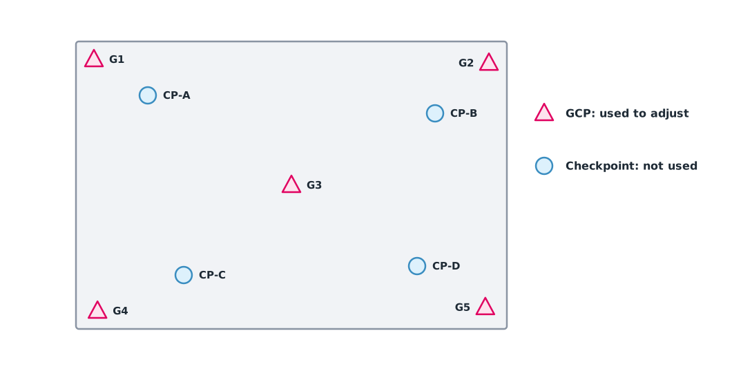
Targets must be clearly visible and identify the same point in several images. Choose stable ground, avoid leaves and vehicles, and never use a shadow as a reference. Spread the points to cover the edges and centre and the high and low ground, not clustered near the take-off point on one side. The OpenDroneMap documentation suggests at least 5 GCPs (8–10 for larger jobs), each visible in at least 3 images, but there is no universal number for every job. The number and distribution must come from the site size, terrain and the agreed criteria.
Height systems
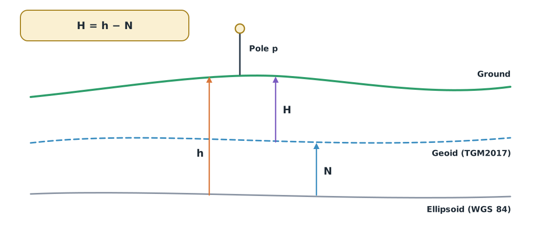
GNSS gives ellipsoidal height (), above a mathematical surface, but surveying and engineering use orthometric height (), referred to mean sea level. The two differ by the geoid height (), as explained by NOAA NGS:
Thailand has the TGM2017 geoid model developed by the Royal Thai Survey Department with Chiang Mai University, used to convert GNSS heights to orthometric heights. Use a model compatible with the job’s datum, and never apply the value from the example to a real site.
Example 1. Point register and height conversion
The receiver reports the antenna height, so the pole height is subtracted first and the result converted to orthometric height. The value in the example is assumed.
points = [  # id, role, E, N, antenna h (m), pole height p (m), pole already subtracted by receiver
    ("G1", "control", 500.00, 1000.00, 52.430, 2.000, False),
    ("G2", "control", 700.00, 1010.00, 53.105, 2.000, False),
    ("C1", "check", 540.00, 1030.00, 50.610, 2.000, True),
    ("C2", "check", 660.00, 1120.00, 52.880, 1.800, False),
]
GEOID_N = -30.000   # assumed training value; read from TGM2017 at the real location

for pid, role, e, n, h_ant, pole, corrected in points:
    h_ground = h_ant if corrected else h_ant - pole
    ortho = h_ground - GEOID_N
    print(f"{pid} {role:<7} h_ground {h_ground:.3f} m  H {ortho:.3f} m")

controls = [p[0] for p in points if p[1] == "control"]
checks = [p[0] for p in points if p[1] == "check"]
print("used for adjustment:", controls, "| kept for checking:", checks)
G1 control h_ground 50.430 m H 80.430 m
G2 control h_ground 51.105 m H 81.105 m
C1 check h_ground 50.610 m H 80.610 m
C2 check h_ground 51.080 m H 81.080 m
used for adjustment: ['G1', 'G2'] | kept for checking: ['C1', 'C2']For C1 the receiver has already subtracted the pole height, so it must not be subtracted again; doing so would put the point 2 m too low. The register therefore needs a column saying whether the pole has been subtracted, and GCPs and checkpoints are kept in separate lists from the start.
Checking before you leave
Before packing up, check that all images open, the time and camera are correct, the targets are clear in the images, the edges of the area are covered and the data is backed up. Coming back to fly again costs many times more than checking in the field.
Example 2. Checking checkpoints after the first processing run
Compare model coordinates with the surveyed values of three checkpoints (synthetic data in a local system).
import math

checks = {  # id: (surveyed E, N, Z), (model E, N, Z)
    "C1": ((500.00, 1000.00, 10.00), (500.03, 999.96, 10.08)),
    "C2": ((600.00, 1000.00, 10.00), (600.00, 1000.06, 9.98)),
    "C3": ((500.00, 1100.00, 11.00), (499.92, 1100.06, 11.04)),
}
for pid, (ref, model) in checks.items():
    de, dn, dz = (round(m - r, 3) for m, r in zip(model, ref))
    print(f"{pid}: dE {de:+.2f}  dN {dn:+.2f}  horizontal {math.hypot(de, dn):.2f} m  dZ {dz:+.2f} m")
C1: dE +0.03 dN -0.04 horizontal 0.05 m dZ +0.08 m
C2: dE +0.00 dN +0.06 horizontal 0.06 m dZ -0.02 m
C3: dE -0.08 dN +0.06 horizontal 0.10 m dZ +0.04 mC3 has a 10 cm horizontal error, almost twice that of the other points. Before concluding the model is wrong, check whether the target was marked at the right spot in the images. One point cannot establish the accuracy of the whole job; combining all points is covered in module 5.
| Finding | What to do | Do not conclude that |
|---|---|---|
| Images missing along one edge | Re-fly only that part when safe | The software will fill the gap correctly |
| A checkpoint hidden by leaves | Use another surveyed point, or collect again | You can move the checkpoint coordinates to match the image |
| GNSS shows fixed | Check the log, reference system and repeat measurements | Fixed means certainly correct |
| All heights differ by the same amount | Check the datum, pole height and pole subtraction | You can subtract a constant without evidence |
Module lab
Lab: point layout and field register
- Plan GCP and checkpoint positions on a map of the training site, spread to the edges and across heights, with a reason for each point
- Place targets, photograph each location and its surroundings, and survey them with GNSS following the instrument manual under experienced supervision, recording the pole height and whether it was subtracted
- Build the point register as in Example 1; leave missing values blank, never zero
- Before leaving, check the images, targets and edges, and record whether to re-fly with reasons
- Submit the point register, the image list and a one-page decision for the instructor to sign
Common mistakes
Watch out
- Reporting the error at GCPs as the map accuracy
- Subtracting the pole height twice when the receiver has already done it
- Mixing ellipsoidal and orthometric heights
- Clustering points near the take-off point without covering the edges and height range
- Entering Z as zero for points whose height was never measured
Summary
- Image positions help processing, GCPs adjust the model and checkpoints are kept aside for an independent check
- Points must be clearly visible, spread across the site and kept in a traceable register
- Subtract the pole height once, then convert with from a suitable geoid model such as TGM2017
- Check the data before leaving the site and decide on re-flights from evidence
Check your understanding
- The antenna height is 45.620 m, the pole is 1.800 m and the receiver has not subtracted it. What is the ground height?
- = 43.820 m and = −28.500 m (assumed). What is the orthometric height?
- A checkpoint has ΔE = −0.06 m and ΔN = +0.08 m. What is the horizontal error?
- What happens to the accuracy assessment if checkpoints are used to adjust the model?
- Does an RTK fixed status certify map accuracy? Why?
Answers
- m
- m
- m
- Those points are no longer independent and the result will look better than it is; a new set of checkpoints is needed
- No, because it does not cover errors from the base-station coordinate, camera set-up or image processing
Key formulas
| Ground height from antenna height | |
| Orthometric height | |
| Horizontal error of a point |
Key references
- OpenDroneMap Authors. Ground control points. OpenDroneMap documentation (Version 3.5). link
- Sampath, A., Shrestha, M., While, M., & Scholl, V. M. (2023). Guidelines for calibration of uncrewed aircraft systems imagery (Open-File Report 2023–1033). U.S. Geological Survey. link
- Milbert, D. G., & Smith, D. A. (1996). Converting GPS height into NAVD88 elevation with the GEOID96 geoid height model. NOAA National Geodetic Survey. link
- Dumrongchai, P., Srimanee, C., Duangdee, N., & Bairaksa, J. (2021). The determination of Thailand Geoid Model 2017 (TGM2017) from airborne and terrestrial gravimetry. Terrestrial, Atmospheric and Oceanic Sciences, 32, 857–872. link
- American Society for Photogrammetry and Remote Sensing. (2024). ASPRS positional accuracy standards for digital geospatial data (Edition 2, Version 2). link
- IOGP. WGS 84 / UTM zone 47N (EPSG:32647). EPSG geodetic parameter dataset. link
Further reading
Study the assigned knowledge units in advance, review media and take the module quiz
In class / field
Intensive lab and field practice recorded in a lab notebook
Learning evidence: Lab notebook signed by the instructor