PLCs and control logic
UAT 202 Fundamentals of Automation Technology
Lesson
By the end of this module you will be able to
- Explain the PLC scan cycle and its effect on response time
- Write ladder logic with NO/NC contacts, coils, seal-in circuits and timers
- Name the IEC 61131-3 programming languages and choose one to suit the task
- Design an emergency stop circuit according to machinery safety principles
Why this matters
A PLC (programmable logic controller) is an industrial computer built to withstand heat, dust and electrical noise and to run continuously for years. Almost every factory machine is controlled by a PLC, and so is the drone battery-swap station. Technicians and engineers who can read and write PLC logic are therefore in demand in both industry and drone work.
The PLC scan cycle
A PLC does not respond the instant an input changes; it works in repeating cycles. According to the Siemens S7-1500 manual, each cycle has four steps:
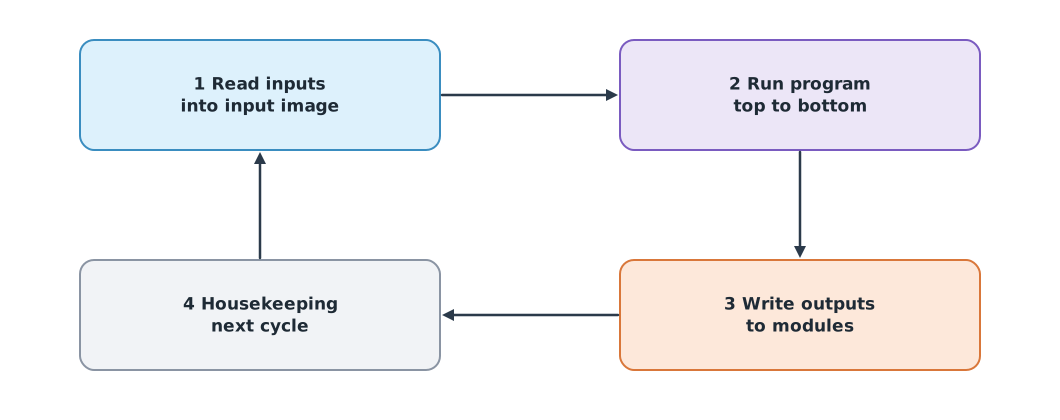
- Read all inputs into the process image
- Run the program from top to bottom using that image
- Write the results to the outputs
- Do system housekeeping and start the next cycle
As a result, an input that changes mid-cycle is seen in the next cycle, so the worst-case response time is about two cycles, and a signal shorter than one cycle may not be seen at all.
Ladder logic
Ladder logic writes programs as rungs of a ladder, like a relay wiring diagram. Per Rockwell’s description:
- A normally open (NO) contact is true when its bit is 1
- A normally closed (NC) contact is true when its bit is 0
- A coil is an output
- Series contacts give AND; parallel contacts give OR
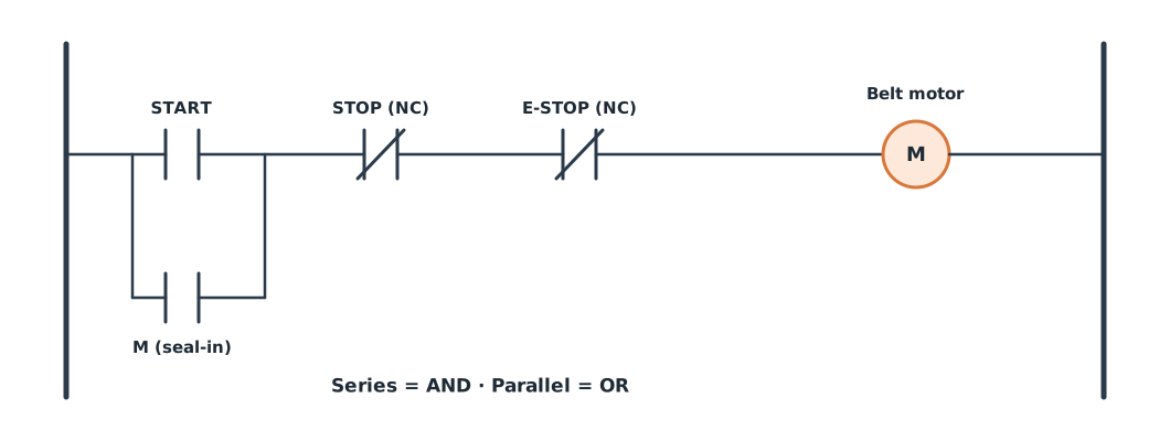
In the seal-in start–stop circuit of Figure 2, pressing START turns the motor on, and the parallel M contact keeps it on after the button is released, until STOP or E-STOP, both wired normally closed, is pressed. The reason: if a stop button’s wire breaks, the circuit stops by itself, which is safer than a normally open wiring where a broken wire means the stop button no longer works.
An on-delay timer (TON) makes its output true when its input has been true continuously for the preset time, used to filter bouncing signals or wait for an object to settle.
Example 1 Simulating the conveyor PLC
The scan cycle is 0.1 s. Rung 1 is the start–stop circuit; rung 2 commands the gripper when a battery has been on the belt continuously for 1.0 s while the belt runs.
DT = 0.1


def inputs_at(t):
    start = 0.5 <= t < 0.7 or 6.0 <= t < 6.2           # short button presses
    stop_ok = not (8.0 <= t < 8.2)                        # NC: True when not pressed
    estop_ok = not (4.0 <= t < 4.5)
    battery = 2.0 <= t < 5.5 or 6.5 <= t < 7.0
    return start, stop_ok, estop_ok, battery


state = {"motor": False, "ton": 0.0, "grip": False}
previous = None
for k in range(100):
    t = round(k * DT, 1)
    start, stop_ok, estop_ok, battery = inputs_at(t)                              # 1 read inputs
    motor = (start or state["motor"]) and stop_ok and estop_ok                     # 2 rung 1
    state["ton"] = state["ton"] + DT if (battery and motor) else 0.0               #   rung 2 (TON)
    grip = state["ton"] >= 1.0 - 1e-9
    state["motor"], state["grip"] = motor, grip                                    # 3 write outputs
    if (motor, grip) != previous:
        print(f"t = {t:4.1f} s  motor {'ON ' if motor else 'OFF'}  gripper {'ON' if grip else 'OFF'}")
        previous = (motor, grip)
t = 0.0 s motor OFF gripper OFF
t = 0.5 s motor ON gripper OFF
t = 2.9 s motor ON gripper ON
t = 4.0 s motor OFF gripper OFF
t = 6.0 s motor ON gripper OFF
t = 8.0 s motor OFF gripper OFFThe motor starts on START and latches. The gripper closes after the battery has been present for a full second. When the emergency stop is pressed at 4 s, everything stops at once and does not restart when the button is released: START must be pressed again. Between 6.5 and 7.0 s the battery is present only half a second, so the timer does not complete and the gripper does not close.
IEC 61131-3 languages and safety
IEC 61131-3 Edition 4 (2025) defines the PLC programming languages Ladder Diagram (LD), Function Block Diagram (FBD), Structured Text (ST), which resembles Pascal, and Sequential Function Chart (SFC) for step-by-step sequences. The former Instruction List language has been removed in the latest edition. The lab uses CODESYS Development System, which is free and includes a simulated PLC on Windows.
An emergency stop is not an ordinary button
ISO 13850 sets principles for designing the emergency stop function, and IEC 60204-1 defines stop Category 0, immediate removal of power; Category 1, a controlled stop followed by removal of power; and Category 2, a controlled stop with power maintained. An emergency stop button must latch when pressed, and the machine must not restart by itself when it is released. Real systems must use certified safety devices, not rely on ordinary PLC programs alone.
Module lab
Lab: programming the conveyor PLC
- Install CODESYS Development System and create a project with a simulated PLC.
- Write the start–stop circuit with E-STOP in LD as in Figure 2, and test every case in a table: press START, release START, press STOP, press E-STOP while running, release E-STOP.
- Add a 1.0 s TON timer for the gripper and compare the results with Example 1.
- Write the same logic in ST and compare readability.
- Shorten the button press in Example 1 below one scan cycle and explain the result.
Common mistakes
Watch out
- Wiring a stop button as normally open, so a broken wire means you cannot stop
- Letting a machine restart by itself after releasing the emergency stop
- Forgetting the seal-in, so the motor runs only while the button is held
- Using pulses shorter than the scan cycle, which the PLC may not see
- Writing the same output in several rungs, so the last rung wins
Summary
- A PLC works in cycles: read inputs, run the program, write outputs, repeat
- Ladder logic uses NO/NC contacts and coils; series is AND, parallel is OR
- A seal-in circuit latches the motor; a TON timer waits for an input to stay true
- IEC 61131-3 has LD, FBD, ST and SFC, and emergency stops must follow safety standards
Check your understanding
- A PLC has a 10 ms scan cycle. What is the approximate worst-case response time?
- Contacts A and B are in series. When is the coil energised?
- Why is the STOP button wired normally closed?
- A TON timer is set to 2 s. Its input is true for 1.5 s then drops. What is the output?
- What is a Category 0 stop under IEC 60204-1?
Answers
- About two cycles, or 20 ms
- When A and B are both true (AND)
- If the wire breaks, the circuit opens and the machine stops, which is safe when damage occurs
- The output does not turn on, because 2 s was not reached continuously and the timer resets
- Immediate removal of power to the actuators
Key formulas
| Start–stop seal-in circuit | |
| On-delay timer (TON) |
Key references
- International Electrotechnical Commission. (2025). Programmable controllers – Part 3: Programming languages (IEC 61131-3:2025, Ed. 4.0). link
- Siemens AG. (2014). SIMATIC S7-1500 cycle and response times: Function manual (A5E03461504-02). link
- Rockwell Automation. Examine if open (XIO) and bit instructions. FactoryTalk Design Studio documentation. link
- CODESYS GmbH. CODESYS Development System V3. link
- International Organization for Standardization. (2015). Safety of machinery — Emergency stop function — Principles for design (ISO 13850:2015). link
- International Electrotechnical Commission. (2021). Safety of machinery – Electrical equipment of machines – Part 1: General requirements (IEC 60204-1:2016+AMD1:2021 CSV). link
- Bolton, W. (2015). Programmable logic controllers (6th ed.). Newnes.
Further reading
Study the assigned knowledge units in advance, review media and take the module quiz
In class / field
Lab or field practice from worksheets with a safety checklist
Learning evidence: Checked worksheets and quiz results