Industrial sensors and actuators
UAT 202 Fundamentals of Automation Technology
Lesson
By the end of this module you will be able to
- Choose inductive, capacitive and photoelectric presence sensors to suit the object and task
- Explain PNP and NPN outputs and connect them to the matching PLC input type
- Convert a 4–20 mA signal to a measurement and detect open wires or sensor faults
- Compare actuators: valves and cylinders, relays and contactors, and stepper and servo motors
Why this matters
The battery-swap station must know when a drone has landed, whether a battery is on the belt, and whether the charging cabinet is too hot. Choose the wrong sensor type, such as a metal-only sensor for a plastic battery case, and the system cannot “see” the battery; wire a sensor to the wrong PLC input type and no signal arrives even though the sensor works.
Presence sensors
| Type | Principle | Detects | Use in the station |
|---|---|---|---|
| Inductive | Electromagnetic field | Metal only | Detecting that the metal gripper arm is in position |
| Capacitive | Electrostatic field | Metal and non-metal, such as plastic, wood and liquids | Detecting the plastic battery case |
| Photoelectric | Light beam | Objects that block or reflect light | Detecting the drone on the landing pad |
Photoelectric sensors come in three types: through-beam, with separate transmitter and receiver and the object blocking the beam; retro-reflective, with transmitter and receiver in one housing and light returned from a reflector; and diffuse, with light reflected from the object itself.
PNP and NPN
A three-wire sensor has a positive supply wire, a negative supply wire and a signal wire. When it detects an object:
- PNP (sourcing) connects the signal wire to the positive supply; current flows out of the sensor into the PLC input
- NPN (sinking) connects the signal wire to the negative supply; current flows into the sensor
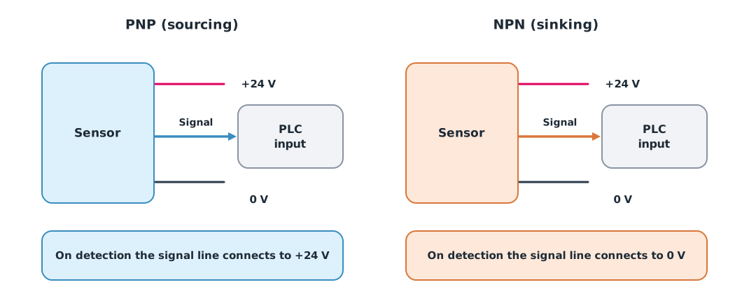
The PLC input must be the matching type: sinking inputs for PNP sensors, and sourcing inputs for NPN sensors. Always check the manuals of both the sensor and the input module, including the supply voltage in that sensor model’s datasheet.
The 4–20 mA signal
Sensors measuring continuous values, such as temperature or pressure, commonly send a 4–20 mA current in industry. Current is the same everywhere in a series loop, so long cables do not distort it as they do a voltage signal. It starts at 4 mA rather than 0 mA (a live zero) so a “true zero” can be told apart from a “broken wire”.
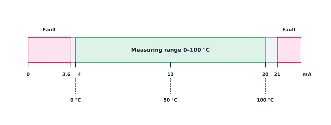
NAMUR recommendation NE 43 standardises signal levels for transmitter failure information. General sources describe values at or below 3.6 mA, or at or above 21 mA, as failures; check these figures against the manual of the transmitter model used.
Example 1 Converting the cabinet temperature signal
The temperature transmitter is ranged 0–100 °C over 4–20 mA.
def to_temperature(ma, lo=0.0, hi=100.0):
    if ma <= 3.6:
        return None, "fault: low (open wire or dead sensor)"
    if ma >= 21.0:
        return None, "fault: high (sensor failure)"
    value = lo + (ma - 4.0) / 16.0 * (hi - lo)
    note = "ok" if 4.0 <= ma <= 20.0 else "outside range, check sensor"
    return value, note


for ma in (4.0, 8.8, 12.0, 20.0, 2.1, 21.5, 3.8):
    value, note = to_temperature(ma)
    shown = f"{value:6.1f} °C" if value is not None else "   ---  "
    print(f"{ma:5.1f} mA -> {shown}  {note}")
4.0 mA -> 0.0 °C ok
8.8 mA -> 30.0 °C ok
12.0 mA -> 50.0 °C ok
20.0 mA -> 100.0 °C ok
2.1 mA -> --- fault: low (open wire or dead sensor)
21.5 mA -> --- fault: high (sensor failure)
3.8 mA -> -1.3 °C outside range, check sensor2.1 mA does not mean a sub-zero temperature; it means a broken wire or dead sensor. The program must report a fault and make the system safe, for example by stopping charging, rather than computing a temperature. 3.8 mA lies between the measuring range and the failure band, so the program still computes a value (−1.3 °C) but warns to check the sensor.
Actuators
- Solenoid valves and pneumatic cylinders: electricity switches a valve, which lets compressed air push a piston. A single-acting cylinder extends with air and returns by spring; a double-acting cylinder uses air both to extend and retract. The station’s battery gripper uses this
- Relays and contactors: a small signal switches a large circuit; a contactor is a large relay for high-power loads such as motors
- Stepper and servo: a stepper motor turns in steps according to pulses, usually without position feedback (open loop), while a servo has an encoder that measures position and corrects it (closed loop). Steppers are cheaper, but if overloaded they can lose steps without the controller knowing
Module lab
Lab: testing sensors and actuators on the training rig
- Test the inductive, capacitive and photoelectric sensors with a metal object, a plastic object and the battery case, recording detection distances.
- Read the labels on the sensors and PLC input module, identify PNP or NPN and sinking or sourcing, then wire them under the instructor’s supervision (power off before every connection).
- Use a signal simulator or multimeter to measure a 4–20 mA loop at 4, 12 and 20 mA, and check against the code in Example 1.
- Disconnect one 4–20 mA signal wire, observe the reading, and check that the program reports a fault.
- Command a solenoid valve to move a cylinder, record the travel time, and note whether it is single or double acting.
Common mistakes
Watch out
- Using an inductive sensor for plastic objects
- Wiring a PNP sensor to a non-matching input type
- Converting signals below 4 mA into a measurement instead of reporting a fault
- Switching a high-power motor directly with a small relay
- Using a stepper where exact position matters without position checking
Summary
- Inductive sensors detect metal, capacitive sensors both metal and non-metal, and photoelectric sensors use three beam arrangements
- PNP connects the signal to the positive supply and NPN to the negative, and must match the PLC input
- 4–20 mA starts at 4 mA to tell zero from a broken wire, and out-of-range signals must be reported as faults
- Choose actuators by load and whether position must be measured
Check your understanding
- To detect a plastic battery case, should you use an inductive or a capacitive sensor?
- A 0–100 °C transmitter sends 16 mA. What is the temperature?
- A 0–10 bar transmitter sends 6 mA. What is the pressure?
- How should a reading of 0.5 mA be interpreted?
- When it detects an object, what does a PNP sensor connect its signal wire to?
Answers
- Capacitive, because inductive sensors detect metal only
- °C
- bar
- A fault, such as a broken wire or unpowered sensor, not a measurement
- The positive supply (sourcing)
Key formulas
| Converting 4–20 mA to a measurement |
Key references
- ifm electronic. Proximity sensors explained: types, applications and benefits. link
- KEYENCE. Photoelectric sensors. link
- Fluke Corporation. What is a 4-20 mA current loop? link
- NAMUR. (2021). NE 43: Standardization of the signal level for the failure information of digital transmitters. link
- Oriental Motor. The choice between servo motors and stepper motors. link
- Bolton, W. (2015). Programmable logic controllers (6th ed.). Newnes.
Further reading
Study the assigned knowledge units in advance, review media and take the module quiz
Industrial automation and PLCs
Calibration and measurement uncertainty
In class / field
Lab or field practice from worksheets with a safety checklist
Learning evidence: Checked worksheets and quiz results