Wiring, connectors and PCBs
UAT 203 Electrical and Electronic Systems for UAS
Lesson
By the end of this module you will be able to
- Choose wire sizes from resistance, voltage drop and heating
- Choose connectors by the current ratings in the manufacturer's datasheet
- Estimate PCB trace widths and use KiCad ERC and DRC
- Lay out high-current wiring and devices to reduce compass interference
Why this matters
Wires and connectors are the most frequent failure points of a drone’s electrical system. Undersized wires heat up and drop voltage; loose or under-rated connectors get hot enough to melt their plastic; and high-current wires near the compass make the drone misjudge its heading and circle. These details look small, but they decide whether a well-designed system actually works.
Choosing wire size
The resistance of copper wire at 20 °C from NBS Handbook 100 (annealed copper wire tables) is, for example, 3.277 Ω/km for 10 AWG, 5.21 Ω/km for 12 AWG, 8.28 Ω/km for 14 AWG and 13.2 Ω/km for 16 AWG. The lower the AWG number, the larger the wire. In a DC circuit, count the length of both the positive and negative wires.
Example 1 The battery lead at maximum current
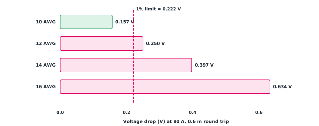
The lead from battery to PDB is 0.3 m long (0.6 m there and back), the maximum current is 80 A, and the voltage drop should not exceed 1% of 22.2 V.
ohm_per_km = {10: 3.277, 12: 5.21, 14: 8.28, 16: 13.2}   # NBS Handbook 100, copper at 20 °C
amps, length_m, limit_v = 80, 0.6, 0.01 * 22.2
for awg, r_km in ohm_per_km.items():
    r = r_km * length_m / 1000
    drop, heat = amps * r, amps ** 2 * r
    verdict = "ok" if drop <= limit_v else "too small"
    print(f"{awg} AWG: {r * 1000:.2f} mΩ, drop {drop:.3f} V, heat {heat:.1f} W -> {verdict}")
10 AWG: 1.97 mΩ, drop 0.157 V, heat 12.6 W -> ok
12 AWG: 3.13 mΩ, drop 0.250 V, heat 20.0 W -> too small
14 AWG: 4.97 mΩ, drop 0.397 V, heat 31.8 W -> too small
16 AWG: 7.92 mΩ, drop 0.634 V, heat 50.7 W -> too smallOnly 10 AWG meets the 1% limit (0.222 V). A 16 AWG lead would dissipate about 51 W at maximum current, which is dangerous. Copper resistance rises as it heats, so real values in use are slightly worse.
Connectors
A connector’s current rating must come from the manufacturer’s datasheet, not the number in the model name or the advertising. Amass’s datasheets, for example, rate the XT60H-M (2025 edition) at 35 A with 12 AWG wire, and the XT90H-M at 45 A (90 A momentary) with 10 AWG. The “90” in XT90 is therefore not a continuous current. A survey drone with a peak near 100 A needs connectors rated for it, or its peak current limited below the rating.
PCB traces
Distribution boards and add-on boards use copper traces instead of wires. The IPC-2221 formula used by PCB makers’ calculators is , where is the cross-section (square mils), the temperature rise (°C) and for outer layers. IPC-2152 (2009) is the dedicated standard for trace current capacity and should be used for real work.
k, delta_t, amps = 0.048, 10, 5                    # outer layer, °C, A
area_mil2 = (amps / (k * delta_t ** 0.44)) ** (1 / 0.725)
thickness_mil = 1.378                              # 1 oz/ft² copper
width_mil = area_mil2 / thickness_mil
print(f"{amps} A, +{delta_t} °C: area {area_mil2:.0f} mil², width {width_mil:.0f} mil = {width_mil * 0.0254:.2f} mm")
5 A, +10 °C: area 150 mil², width 109 mil = 2.77 mmIn KiCad (version 10, GPL licence), ERC checks the schematic, for example for unconnected power pins, and DRC checks the board, for example for traces narrower than the rules or too close together. Set the width rule for power nets to match the calculation.
Reducing compass interference
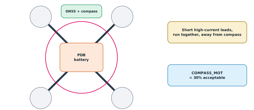
High current in wires creates magnetic fields that disturb the compass. Keep high-current leads as short as possible, run positive and negative together so their fields cancel, and mount the compass on a mast away from the PDB and battery. ArduPilot’s CompassMot procedure measures interference from motors and power wires: under 30% is acceptable, 31–60% is a grey zone, and above 60% the unit should be moved or an external compass used.
Module lab
Lab: wiring harness and distribution board
- Measure the training drone’s battery and ESC lead lengths and check the wire sizes used with the code in Example 1.
- Read the datasheet of every connector on the training drone and compare its rating with the peak current from module 1.
- Practise soldering XT60 connectors to wire of the specified size under the instructor’s supervision, then check strength and insulation.
- Draw the schematic and board of a small distribution board in KiCad, set trace widths to the calculation, and pass ERC and DRC.
- In SITL or on a real drone (as the instructor directs), study the CompassMot procedure and record the result.
Common mistakes
Watch out
- Counting only one wire’s length, forgetting the return
- Trusting the number in a connector’s name instead of its datasheet rating
- Cold solder joints, leaving loose connectors with high resistance and heat
- Mounting the compass near the PDB or battery leads
- Skipping ERC and DRC before ordering boards
Summary
- Choose wire size from resistance per length, voltage drop and heat, counting both directions
- Connector ratings must come from the manufacturer’s datasheet
- Estimate traces with the IPC-2221 formula, check against IPC-2152, and verify designs with ERC and DRC
- High-current leads should be short, run together and away from the compass; CompassMot under 30% is acceptable
Check your understanding
- What is the resistance of 12 AWG wire 1 m long in total?
- That wire carries 40 A. What are the voltage drop and heat?
- Why is the number in the name XT90 not the continuous current to design with?
- Which KiCad check finds traces that are too close together?
- What should you do if CompassMot shows 70%?
Answers
- mΩ
- V and W
- The manufacturer’s datasheet gives a 45 A continuous rating; 90 A is momentary
- DRC (design rules check)
- Above 60%, move the flight controller or compass, or use an external compass away from high-current wiring
Key formulas
| Wire resistance | |
| Wire voltage drop and loss | |
| IPC-2221 trace estimate |
Key references
- National Bureau of Standards. (1966). Copper wire tables (Handbook 100). link
- Amass. XT60H-M connector specification (2025V0). link
- Amass. XT90H-M connector specification (V1.2). link
- IPC. (2009). Standard for determining current carrying capacity in printed board design (IPC-2152). link
- KiCad Developers. KiCad EDA (version 10). link
- ArduPilot Dev Team. Advanced compass setup (CompassMot). ArduPilot Copter documentation. link
- Horowitz, P., & Hill, W. (2015). The art of electronics (3rd ed.). Cambridge University Press.
Further reading
Study the assigned knowledge units in advance, review media and take the module quiz
In class / field
Lab or field practice from worksheets with a safety checklist
Learning evidence: Checked worksheets and quiz results