PID controllers
UAT 206 Fundamentals of Control and Autopilot Systems
Lesson
By the end of this module you will be able to
- Write a digital PID controller and distinguish the parallel and standard forms
- Prevent integral windup when the control signal saturates
- Use derivative on measurement and derivative filtering to reduce control peaks
- Choose starting gains and explain the effect of P, I and D on the response
Why this matters
The textbook PID formula is short, but a controller that really flies must handle things the formula does not mention: commands beyond the motors’ limits, sudden setpoint changes and sensor noise. Chapter 11 of Åström and Murray (2021) and Åström and Hägglund (2006) cover these in detail, and PX4 uses the same techniques in its own control loops.
Two forms of PID
- Parallel form: three separate gains .
- Standard (ideal) form: an overall gain multiplying all three terms.
The PX4 PID tuning guide explains that the rate loop supports both: setting MC_ROLLRATE_K = 1 gives the parallel form, while setting P = 1 gives the standard form, which separates the overall gain from the I and D tuning. Know which form is in use before borrowing gains from elsewhere.
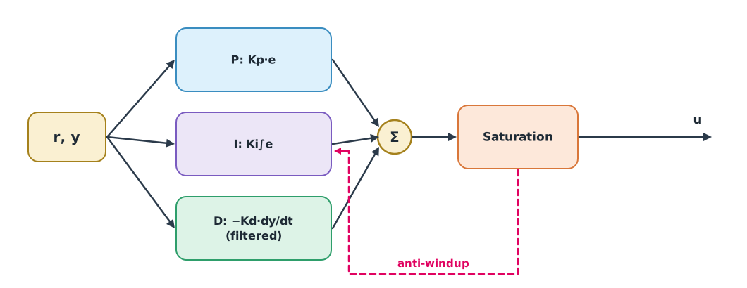
Integral windup
Motors can only give so much thrust. When the command exceeds the limit, the actual signal saturates, but the I term keeps accumulating error. Once the target is reached, the large accumulated I pushes far past it: integral windup. Two common fixes:
- Clamping: stop integrating while saturated and the error still pushes the same way. PX4 uses this in its velocity loop (Controller Diagrams).
- Back-calculation: feed the difference between the command and the saturated value back to reduce I (Åström and Murray, section 11.4).
Example 1 Altitude control with saturated thrust
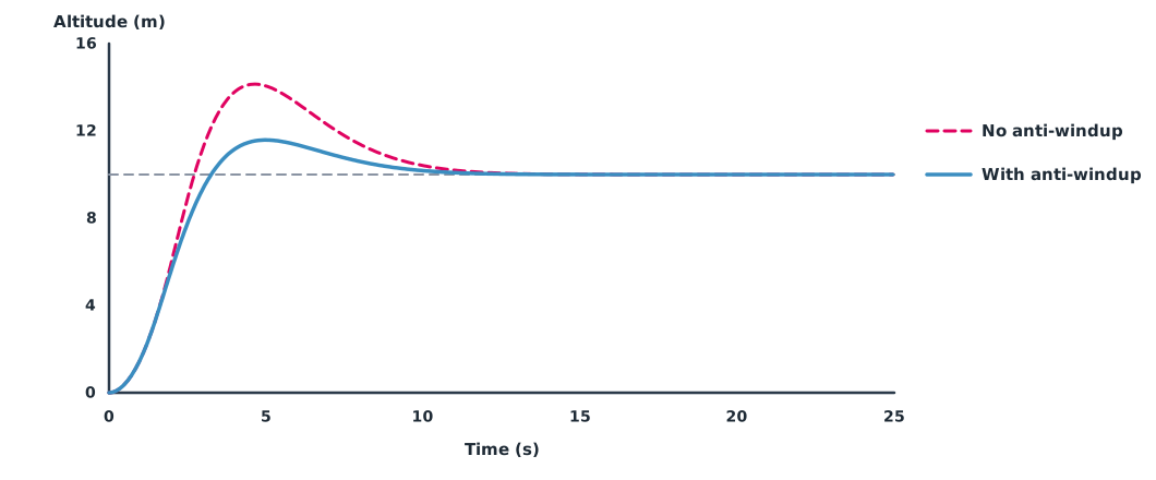
A climb from 0 to 10 m is commanded; the acceleration command is limited to ±3 m/s² because thrust is limited.
KP, KI, KD, AMAX, DT = 1.5, 0.4, 2.0, 3.0, 0.01

def climb(anti_windup):
    z = v = integ = 0.0
    zs = []
    for _ in range(int(40 / DT)):
        e = 10 - z
        a_cmd = KP * e + KI * integ - KD * v
        a = max(-AMAX, min(AMAX, a_cmd))
        pushing_further = (a_cmd > AMAX and e > 0) or (a_cmd < -AMAX and e < 0)
        if not (anti_windup and pushing_further):
            integ += e * DT
        v += a * DT
        z += v * DT
        zs.append(z)
    settle = next(i * DT for i in range(len(zs)) if all(abs(x - 10) <= 0.2 for x in zs[i:]))
    return max(zs) - 10, settle

for label, flag in (("without anti-windup", False), ("with clamping", True)):
    over, ts = climb(flag)
    print(f"{label:<20} overshoot {over:.2f} m, within 0.2 m after {ts:.1f} s")
without anti-windup overshoot 4.14 m, within 0.2 m after 11.0 s
with clamping overshoot 1.58 m, within 0.2 m after 9.8 sClamping cuts overshoot by more than half. The remaining overshoot comes from speed built up while climbing at full acceleration, which is fixed by limiting climb rate in the outer loop.
Derivative on measurement and filtering
If the D term uses the error, a setpoint step makes the derivative spike momentarily. Åström and Murray recommend applying D (and possibly P) to the measurement instead, called setpoint weighting. Also, the derivative amplifies high-frequency noise, so it must be filtered: with and around 5–20. PX4 applies a low-pass filter to the D term of the rate loop.
Example 2 Control peaks on a setpoint change
The setpoint steps from 0 to 10 while the measurement is still 0, with 10 ms steps; only the D term is shown.
KP, KD, DT, N = 1.5, 2.0, 0.01, 10
TF = (KD / KP) / N                     # s derivative filter time constant

steps = [0.0, 10.0, 10.0, 10.0]        # setpoint at each time step
meas = [0.0, 0.0, 0.02, 0.08]          # measurement (just starting to move)

def d_term(signal, sign, filtered):
    d, peak = 0.0, 0.0
    for k in range(1, len(signal)):
        raw = sign * KD * (signal[k] - signal[k - 1]) / DT
        d = d + DT / (TF + DT) * (raw - d) if filtered else raw
        peak = max(peak, abs(d))
    return peak

err = [r - y for r, y in zip(steps, meas)]
print(f"D on error, unfiltered:   peak {d_term(err, 1, False):7.1f}")
print(f"D on error, filtered N={N}: peak {d_term(err, 1, True):7.1f}")
print(f"D on measurement, filtered: peak {d_term(meas, -1, True):7.1f}")
D on error, unfiltered: peak 2000.0
D on error, filtered N=10: peak 139.5
D on measurement, filtered: peak 1.1The derivative of the error spikes to 2,000, filtering cuts it to about 140, but derivative on measurement stays around 1, removing the problem at its source because the measurement does not jump with the setpoint.
Tuning order
The PX4 guide says to tune the rate loop first, because it affects every flight mode, then the attitude, velocity and position loops. Test with step inputs while hovering; the guide says a well-tuned drone follows immediately without oscillating or overshooting. General guidance:
- P speeds up the response, but too much causes oscillation.
- I removes steady error, such as an offset centre of gravity, but too much causes slow overshoot.
- D damps oscillation but amplifies noise, so filter it and watch motor temperature.
Module lab
Lab: altitude PID in simulation
- Run the code from Example 1, changing KP, KI and KD one at a time, and tabulate overshoot and settling time.
- Add a 2 m/s climb-rate limit in the outer loop and compare overshoot with before.
- Use the code from Example 2 with N between 5 and 20 and watch the D-term peak.
- In the PX4 or ArduPilot documentation, identify which parameters are the rate loop’s P, I, D and filters.
- Write the tuning order you will use in SITL in Module 5.
Common mistakes
Watch out
- Copying standard-form gains into a parallel form without converting.
- No anti-windup when the control signal can saturate.
- Computing D from the error, then wondering why motors twitch on setpoint changes.
- Raising D without filtering until the motors overheat.
- Tuning outer loops before inner loops.
Summary
- PID comes in parallel and standard forms; know which the autopilot uses.
- Clamping or back-calculation anti-windup reduces overshoot under saturation.
- Use derivative on measurement and a filter with ( = 5–20).
- Tune the rate loop first, then the outer loops.
Check your understanding
- A standard-form PID has , s. What is in parallel form?
- When does integral windup occur?
- With , and , what is ?
- Why compute the D term from the measurement rather than the error?
- Which loop does the PX4 guide say to tune first?
Answers
- When the control signal saturates but the I term keeps accumulating error.
- s, so s.
- The measurement does not jump with the setpoint, so there is no control peak.
- The rate loop.
Key formulas
| Parallel PID | |
| Standard (ideal) PID | |
| Derivative filter |
Key references
- Åström, K. J., & Murray, R. M. (2021). Feedback systems: An introduction for scientists and engineers (2nd ed.). Princeton University Press. link
- Åström, K. J., & Hägglund, T. (2006). Advanced PID control. ISA–The Instrumentation, Systems, and Automation Society.
- PX4 Autopilot. Multicopter PID tuning guide. PX4 guide (main). link
- PX4 Autopilot. Controller diagrams. PX4 user guide (main). link
Further reading
Study the assigned knowledge units in advance, review media and take the module quiz
In class / field
Lab or field practice from worksheets with a safety checklist
Learning evidence: Checked worksheets and quiz results