Radio waves and antennas
UAT 207 Communication and Data Network Systems
Lesson
By the end of this module you will be able to
- Compute the first Fresnel zone radius and the mast height needed under ITU-R criteria
- Explain the effect of Earth curvature using the effective Earth radius factor k = 4/3
- Read the radiation pattern of a half-wave dipole and explain the null overhead
- Explain polarization mismatch loss
Why this matters
Earlier courses covered link power budgets, but real links drop for reasons the basic formula does not show: trees that do not block the straight line between antennas yet still absorb energy, or a drone that loses signal while flying right over the station. This module explains these effects with Fresnel zones and antenna radiation patterns.
The whole course uses one hypothetical case: the lab’s mangrove survey team flies a fixed-wing drone up to 5 km away with telemetry and video, and runs a LoRa network at its field station. All numbers are made up for practice unless a source is given. The Python code for every module can be downloaded from /downloads/uat-207/.
Fresnel zones
Radio waves do not travel as a single straight line but spread through a volume around the line between antennas. The most important ellipsoid is the first Fresnel zone, widest at mid-path. If an obstacle intrudes into it, the signal weakens even though the antennas still see each other, like sound still heard through a door left ajar, but quieter.
Recommendation ITU-R P.530-19 gives metres and sets out a procedure for antenna heights. The first step is to clear the highest obstacle by 1.0 using ; further criteria follow by climate, for example 0.6 in tropical climates for paths longer than about 30 km; the larger resulting height is used.
Earth curvature raises the ground at mid-path, but the atmosphere bends waves partly along the Earth, so an effective Earth radius is used; ITU-R P.834 uses the approximation .
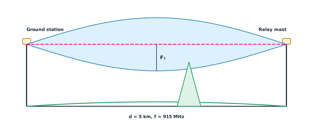
Example 1 Mast height for a 915 MHz link over 5 km
Mangroves 15 m tall stand 3 km from the station over flat ground; both masts are the same height.
import math

F_GHZ, D_KM = 0.915, 5.0
RE_KM, K = 6371.0, 4 / 3
OBSTACLE_M, AT_KM = 15.0, 3.0                  # tree height, distance from the station

def fresnel_m(d1, d2):
    return 17.3 * math.sqrt(d1 * d2 / (F_GHZ * (d1 + d2)))

def bulge_m(d1, d2):
    return d1 * d2 / (2 * K * RE_KM) * 1000

for d1 in (0.5, 1.25, 2.5, AT_KM):
    d2 = D_KM - d1
    print(f"{d1:4.2f} km: F1 {fresnel_m(d1, d2):5.2f} m, earth bulge {bulge_m(d1, d2):.2f} m")

d2 = D_KM - AT_KM
for frac in (1.0, 0.6):
    need = OBSTACLE_M + bulge_m(AT_KM, d2) + frac * fresnel_m(AT_KM, d2)
    print(f"clearance {frac} F1 over the mangroves -> masts at least {math.ceil(need)} m")
0.50 km: F1 12.13 m, earth bulge 0.13 m
1.25 km: F1 17.51 m, earth bulge 0.28 m
2.50 km: F1 20.22 m, earth bulge 0.37 m
3.00 km: F1 19.81 m, earth bulge 0.35 m
clearance 1.0 F1 over the mangroves -> masts at least 36 m
clearance 0.6 F1 over the mangroves -> masts at least 28 mThe Fresnel zone is about 20 m wide at mid-path, while the Earth bulge at this range is under half a metre, so mast height is driven mainly by the Fresnel zone. A drone flying at 120 m clears it easily, but a ground station on a short mast loses signal when the drone descends behind the tree line.
Antenna radiation patterns
Antennas do not radiate equally in every direction. The half-wave dipole, the basic antenna of telemetry radios, has a gain of 2.15 dBi towards the horizon and the pattern , with measured from the antenna axis (Balanis, 2016). Mounted vertically, a dipole has a null, almost no signal, straight up and straight down.
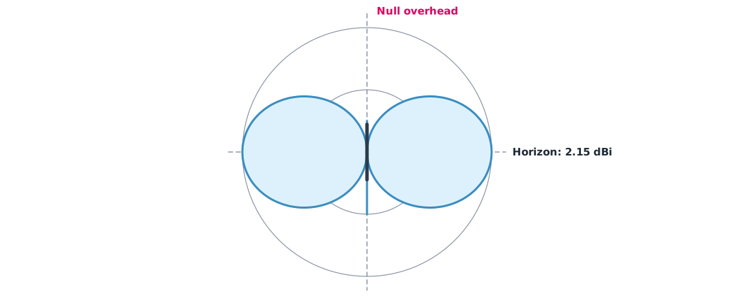
Example 2 Flying in over the station
The drone flies at 120 m towards the station; both ends use vertical dipoles at 915 MHz.
import math

H_M, F_HZ = 120.0, 915e6

def pattern_db(theta):
    return 20 * math.log10(math.cos(math.pi / 2 * math.cos(theta)) / math.sin(theta))

for x in (5000, 1000, 500, 200, 100, 50, 10):
    elev = math.atan2(H_M, x)
    g = pattern_db(math.pi / 2 - elev)          # angle from the antenna axis
    dist = math.hypot(x, H_M)
    fspl = 20 * math.log10(dist) + 20 * math.log10(F_HZ) - 147.55
    print(f"ground range {x:>4} m: elevation {math.degrees(elev):4.1f} deg, pattern loss both ends "
          f"{-2 * g:5.1f} dB, FSPL {fspl:5.1f} dB, total {fspl - 2 * g:5.1f} dB")
ground range 5000 m: elevation 1.4 deg, pattern loss both ends 0.0 dB, FSPL 105.7 dB, total 105.7 dB
ground range 1000 m: elevation 6.8 deg, pattern loss both ends 0.2 dB, FSPL 91.7 dB, total 91.9 dB
ground range 500 m: elevation 13.5 deg, pattern loss both ends 0.7 dB, FSPL 85.9 dB, total 86.6 dB
ground range 200 m: elevation 31.0 deg, pattern loss both ends 3.8 dB, FSPL 79.0 dB, total 82.8 dB
ground range 100 m: elevation 50.2 deg, pattern loss both ends 10.2 dB, FSPL 75.6 dB, total 85.7 dB
ground range 50 m: elevation 67.4 deg, pattern loss both ends 20.2 dB, FSPL 74.0 dB, total 94.1 dB
ground range 10 m: elevation 85.2 deg, pattern loss both ends 47.4 dB, FSPL 73.3 dB, total 120.7 dBWith the drone almost overhead, the total loss is worse than at 5 km away, because both ends point their weakest pattern directions at each other. Fixes include siting the station so the drone does not pass straight over the mast, fitting several antennas at different angles on the drone, or tilting the ground antenna towards the flight area.
Polarization
Both antennas should share the same polarization, for example both vertical. If they are tilted apart by an angle , received power is multiplied by (Balanis, 2016): 45° loses half, or 3 dB, and at right angles, in theory, nothing is received. When the drone banks, its antenna tilts with it, which is why circularly polarized antennas, insensitive to tilt, are popular for video links.
Module lab
Lab: path survey and antenna tests
- Using an elevation map or a field survey, draw the path profile from the station to the farthest flight point.
- Use the code from Example 1 to find the required mast height and compare with the mast available.
- Fly the drone over the station at constant height, record RSSI from telemetry and compare with Example 2.
- Rotate the ground antenna to 0°, 45° and 90° and record the received signal.
- Follow Thailand’s frequency and power rules in every experiment.
Common mistakes
Watch out
- Checking line of sight only without allowing for the Fresnel zone.
- Assuming signal is always good close to the station.
- Mounting antennas at different tilts.
- Forgetting that trees grow and wet leaves absorb more.
- Entering MHz or metres into a formula that expects GHz and km.
Summary
- The first Fresnel zone is widest at mid-path; ITU-R P.530 starts with 1.0 clearance at .
- Over a few kilometres, Earth bulge matters far less than the Fresnel zone.
- A vertical dipole has a null overhead, so a drone over the station can lose signal.
- Polarization misaligned by reduces power by .
Check your understanding
- What is the mid-path radius for a 4 km link at 2.4 GHz?
- How does the Fresnel zone radius change as frequency rises?
- In which directions does a vertical dipole have nulls?
- Antennas are tilted 60° apart. How many dB are lost?
- Why can a drone close to the station have a worse signal than when it is far away?
Answers
- m
- It shrinks, in inverse proportion to the square root of frequency.
- Straight up and straight down along the antenna axis.
- , about 6 dB.
- The drone is in the null of both antennas, so the gain drops sharply.
Key formulas
| First Fresnel zone radius | |
| Earth bulge height | |
| Half-wave dipole pattern |
Key references
- International Telecommunication Union. (2025). Propagation data and prediction methods required for the design of terrestrial line-of-sight systems (Recommendation ITU-R P.530-19). link
- International Telecommunication Union. (2017). Effects of tropospheric refraction on radiowave propagation (Recommendation ITU-R P.834-9). link
- International Telecommunication Union. (2024). Calculation of free-space attenuation (Recommendation ITU-R P.525-5). link
- Balanis, C. A. (2016). Antenna theory: Analysis and design (4th ed.). Wiley. link
Further reading
Study the assigned knowledge units in advance, review media and take the module quiz
In class / field
Lab or field practice from worksheets with a safety checklist
Learning evidence: Checked worksheets and quiz results