Drawing standards
UAT 208 Digital Drafting and Prototyping Technology
Lesson
By the end of this module you will be able to
- Read and lay out first-angle and third-angle projections per ISO 5456-2
- Apply ISO 2768-1 general tolerances to dimensions without individual tolerances
- Compute worst-case and RSS tolerance stack-ups
- Read ISO 286 fits and choose screw clearance holes per ISO 273
Why this matters
An engineering drawing is the common language between designer, printer operator and inspector. Read the views the wrong way round and the part comes out mirrored; leave out tolerances and nobody knows how much deviation is acceptable, so printed parts may not fit together. This course uses one hypothetical case throughout: the lab designs and prints a camera mount and a prototype drone arm in PLA. Numbers are hypothetical unless a source is given. The Python code can be downloaded from /downloads/uat-208/.
Projections and lines
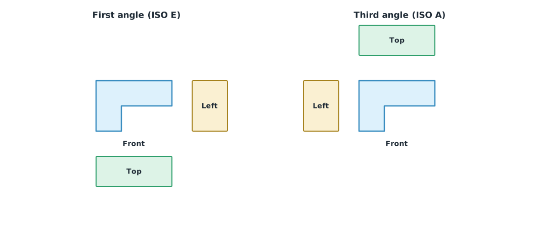
The ISO 128 series (2020 editions) sets the principles of drawing, such as line types and sections. ISO 5456-2 sets out orthographic view layouts, with two systems you must tell apart:
- First angle, common in Europe and Asia: the top view goes below the front view, and the left-side view goes on the right.
- Third angle, common in North America: the top view goes above the front view, and the left-side view goes on the left.
A drawing must carry the projection symbol (a truncated cone and concentric circles) in the title block to show which system is used. Dimensioning follows ISO 129-1. Giesecke et al. (2023) explain both systems with examples.
General tolerances and stack-ups
Every size has a tolerance, the range by which the real size may differ from the stated size. If not every dimension is toleranced individually, general tolerances from ISO 2768-1 apply, noted in the title block as, for example, “ISO 2768-m”. The table gives values by size range and class f (fine), m (medium), c (coarse), v (very coarse). The standard also states that a part exceeding a general tolerance is not rejected automatically if its function is unaffected.
When several parts stack, deviations accumulate. The worst-case method adds tolerances directly: safe but overly cautious. The RSS method assumes each part’s deviation is independent and centred, so it adds them as the root sum of squares: narrower, but with a small chance of exceeding the result.
Example 1 Four plates stacked in a mount slot
Four 3.0 mm plates go into a 12.5 mm slot; every size uses ISO 2768-m.
import math

ISO2768 = {                                   # class: [(upper bound of range mm, tolerance ± mm), ...]
    "f": [(3, 0.05), (6, 0.05), (30, 0.1), (120, 0.15), (400, 0.2), (1000, 0.3)],
    "m": [(3, 0.1), (6, 0.1), (30, 0.2), (120, 0.3), (400, 0.5), (1000, 0.8)],
    "c": [(3, 0.2), (6, 0.3), (30, 0.5), (120, 0.8), (400, 1.2), (1000, 2.0)],
}

def general_tol(size_mm, cls="m"):
    return next(t for upper, t in ISO2768[cls] if size_mm <= upper)

for size in (2.5, 5, 25, 60, 150):
    print(f"{size:>5} mm: f ±{general_tol(size, 'f')}, m ±{general_tol(size, 'm')}, c ±{general_tol(size, 'c')}")

plates = [3.0] * 4
slot = 12.5
t_plate = [general_tol(p) for p in plates]
t_slot = general_tol(slot)
gap = slot - sum(plates)
worst = t_slot + sum(t_plate)
rss = math.sqrt(t_slot ** 2 + sum(t * t for t in t_plate))
print(f"nominal gap {gap:.2f} mm, worst case ±{worst:.2f} -> min {gap - worst:+.2f} mm")
print(f"RSS ±{rss:.3f} -> min {gap - rss:+.3f} mm")
2.5 mm: f ±0.05, m ±0.1, c ±0.2
5 mm: f ±0.05, m ±0.1, c ±0.3
25 mm: f ±0.1, m ±0.2, c ±0.5
60 mm: f ±0.15, m ±0.3, c ±0.8
150 mm: f ±0.2, m ±0.5, c ±1.2
nominal gap 0.50 mm, worst case ±0.60 -> min -0.10 mm
RSS ±0.283 -> min +0.217 mmIn the worst case the plates might not fit, but by RSS a gap remains. The team must decide whether to accept the risk or change the design, for example by widening the slot or tightening its tolerance. 3D-printed parts often deviate more than class m, so real measurement follows in Module 5.
Fits and screw clearance holes
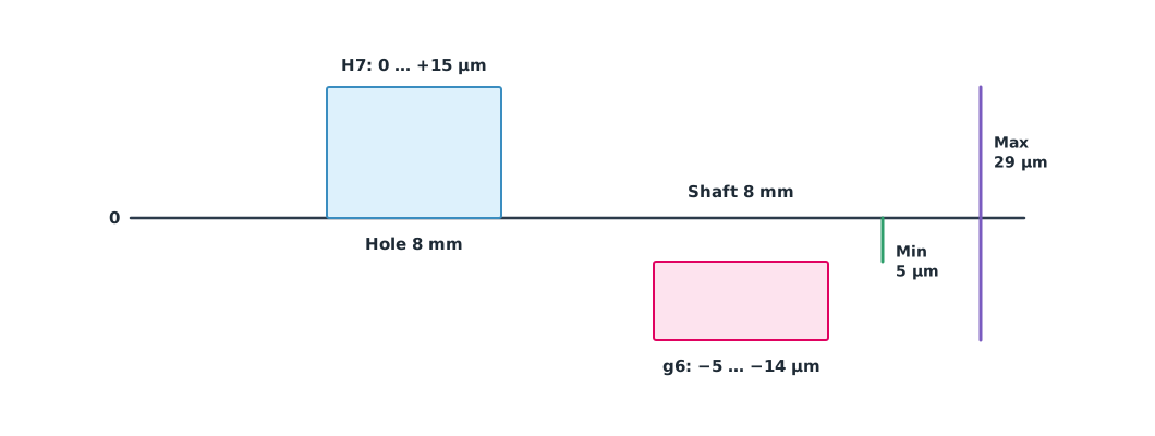
When a shaft goes into a hole, such as a bearing shaft or a hinge pin, the ISO 286 fit system is used. Hole and shaft codes set the position and width of the tolerance zones. Per ISO 286-2, for sizes over 6 up to 10 mm, an H7 hole is 0 to +15 µm and a g6 shaft is −5 to −14 µm, a small-clearance fit that can rotate.
For screw holes, ISO 273 gives three clearance hole series; for M3, holes of 3.2 mm (fine), 3.4 mm (medium) and 3.6 mm (coarse).
Example 2 Fit clearance and M3 clearance holes
HOLE_H7 = (0.0, 0.015)                   # mm, 6–10 mm range per ISO 286-2
SHAFT_G6 = (-0.014, -0.005)
c_min = HOLE_H7[0] - SHAFT_G6[1]
c_max = HOLE_H7[1] - SHAFT_G6[0]
print(f"8 H7/g6: clearance {c_min * 1000:.0f} to {c_max * 1000:.0f} µm")

ISO273_M3 = {"fine": 3.2, "medium": 3.4, "coarse": 3.6}
for series, hole in ISO273_M3.items():
    print(f"M3 {series:<6}: hole {hole} mm, diametral clearance {hole - 3.0:.1f} mm")
8 H7/g6: clearance 5 to 29 µm
M3 fine : hole 3.2 mm, diametral clearance 0.2 mm
M3 medium: hole 3.4 mm, diametral clearance 0.4 mm
M3 coarse: hole 3.6 mm, diametral clearance 0.6 mmThis fit’s clearance is measured in micrometres, which an FDM printer cannot achieve directly. For such a fit, print the hole undersize and ream it, or press in a metal bushing. Printed screw holes usually start from the medium series and are then compensated from measurements.
Module lab
Lab: drawing the camera mount
- Sketch three views of the camera mount in both first-angle and third-angle layouts, including the projection symbol.
- Dimension per ISO 129-1 and note “ISO 2768-m” in the title block.
- Use the code from Example 1 to check the tolerance stack-up of stacked parts.
- Choose screw hole sizes per ISO 273 and record the reasoning.
- Swap drawings with a classmate to read, and record anything misread or missing.
Common mistakes
Watch out
- Leaving out the projection symbol.
- Over-dimensioning, so tolerances conflict.
- Using RSS when all parts deviate the same way.
- Specifying micrometre fits for FDM parts.
- Forgetting units and the general tolerance standard.
Summary
- First angle places the top view below the front view, third angle above; always include the projection symbol.
- ISO 2768-1 gives general tolerances by size range, for example ±0.2 mm for class m, 6–30 mm.
- Worst-case stack-ups add directly; RSS adds as the root sum of squares.
- An 8 H7/g6 fit has 5–29 µm clearance, and ISO 273 M3 holes are 3.2/3.4/3.6 mm.
Check your understanding
- In third angle, where does the top view go?
- What deviation does ISO 2768-m allow on a 45 mm dimension?
- Five parts each ±0.1 mm: what are the worst-case and RSS stack-ups?
- An 8 mm H7 hole with an h6 shaft (h6 = 0 to −9 µm): what is the minimum clearance?
- What is the ISO 273 medium clearance hole for M3?
Answers
- Above the front view.
- ±0.3 mm (30–120 mm range).
- Worst case ±0.5 mm; RSS mm.
- µm (they may just touch).
- 3.4 mm.
Key formulas
| Worst-case stack-up | |
| RSS stack-up | |
| Fit clearance |
Key references
- Giesecke, F. E., Lockhart, S., Goodman, M., & Johnson, C. M. (2023). Technical drawing with engineering graphics (16th ed.). Pearson. link
- International Organization for Standardization. (2020). Technical product documentation (TPD) — General principles of representation — Part 1: Introduction and fundamental requirements (ISO 128-1:2020). link
- International Organization for Standardization. (1996). Technical drawings — Projection methods — Part 2: Orthographic representations (ISO 5456-2:1996). link
- International Organization for Standardization. (2018). Technical product documentation (TPD) — Presentation of dimensions and tolerances — Part 1: General principles (ISO 129-1:2018). link
- International Organization for Standardization. (1989). General tolerances — Part 1: Tolerances for linear and angular dimensions without individual tolerance indications (ISO 2768-1:1989). link
- International Organization for Standardization. (2010). Geometrical product specifications (GPS) — ISO code system for tolerances on linear sizes — Part 2: Tables of standard tolerance classes and limit deviations for holes and shafts (ISO 286-2:2010). link
- International Organization for Standardization. (1979). Fasteners — Clearance holes for bolts and screws (ISO 273:1979). link
Further reading
Study the assigned knowledge units in advance, review media and take the module quiz
In class / field
Lab or field practice from worksheets with a safety checklist
Learning evidence: Checked worksheets and quiz results