Parametric CAD
UAT 208 Digital Drafting and Prototyping Technology
Lesson
By the end of this module you will be able to
- Build fully constrained sketches and explain degrees of freedom
- Drive geometry from a parameter table according to design intent
- Choose CAD source, STEP, STL and 3MF files appropriately
- Compute STL triangle count and file size from the chord tolerance
Why this matters
A camera mount changes often: a new camera means new hole spacing, a different screw means a new clearance hole. Redrawing the shape by hand every time is slow and error-prone. Parametric CAD keeps the design intent in variables and relationships, so changing one value updates the whole shape. The drone knowledge base’s CAD and 3D printing unit and lab L05 use the camera mount as the same example.
Sketches, constraints and degrees of freedom
Every feature starts from a 2D sketch, and each element has degrees of freedom (DOF). The FreeCAD Sketcher guide explains that an unconstrained line has 4 DOF (two end points, 2 each). Adding constraints such as horizontal, point lock and length until the DOF reach zero makes the sketch fully constrained, so the shape does not change unexpectedly when parameters are edited. Use constraints that express intent, such as two equal holes or symmetry about an axis, rather than placing things by eye.
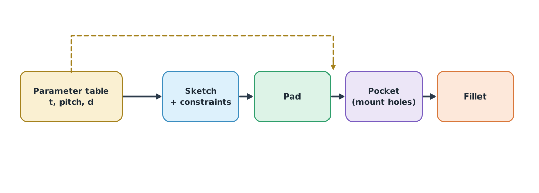
Example 1 A parameter-driven camera mount
The team sets its own design rules: the distance from an edge to a hole centre must be at least twice the hole diameter, and the plate at least 3 mm thick (team rules, not a standard).
ISO273_MEDIUM = {"M2": 2.4, "M2.5": 2.9, "M3": 3.4, "M4": 4.5}   # mm medium clearance holes
T_MIN, EDGE_FACTOR, DENSITY = 3.0, 2.0, 1.24e-3                   # mm, times the hole size, g/mm³

def mount(pitch, screw="M3", t=3.0, depth=20.0):
    hole = ISO273_MEDIUM[screw]
    edge = EDGE_FACTOR * hole
    width = pitch + 2 * edge
    volume = width * depth * t - 2 * 3.14159 * (hole / 2) ** 2 * t
    ok = t >= T_MIN
    return hole, width, volume * DENSITY, ok

for pitch, screw in ((16, "M2"), (20, "M3"), (25.5, "M3"), (25.5, "M4")):
    hole, width, mass, ok = mount(pitch, screw)
    print(f"pitch {pitch:>4} mm, {screw:<4}: hole {hole} mm, plate width {width:.1f} mm, "
          f"mass {mass:.2f} g, thickness rule {'ok' if ok else 'FAIL'}")
pitch 16 mm, M2 : hole 2.4 mm, plate width 25.6 mm, mass 1.87 g, thickness rule ok
pitch 20 mm, M3 : hole 3.4 mm, plate width 33.6 mm, mass 2.43 g, thickness rule ok
pitch 25.5 mm, M3 : hole 3.4 mm, plate width 39.1 mm, mass 2.84 g, thickness rule ok
pitch 25.5 mm, M4 : hole 4.5 mm, plate width 43.5 mm, mass 3.12 g, thickness rule okChanging only the hole spacing and screw size updates plate width and mass automatically. In real CAD these relationships live in a parameter table (spreadsheet) that the sketch refers to.
File formats
- CAD source (such as .FCStd) keeps features, constraints and parameters; it can be edited further and must always be kept.
- STEP (ISO 10303-21) stores exact curved geometry for exchange between CAD programs, without feature history.
- STL stores the surface as triangles. The binary form has an 80-byte header, a 4-byte triangle count and 50 bytes per triangle, and carries no units.
- 3MF (3MF Consortium) stores the mesh with units, colours, materials and print settings.
The knowledge base unit stresses that having only an STL is not the same as having the full design history.
STL resolution
When exporting STL, the program replaces curved surfaces with triangles. The largest distance between the true surface and the triangles is the chord error, or surface deviation (FreeCAD Mesh guide). The smaller it is, the smoother the shape but the bigger the file.
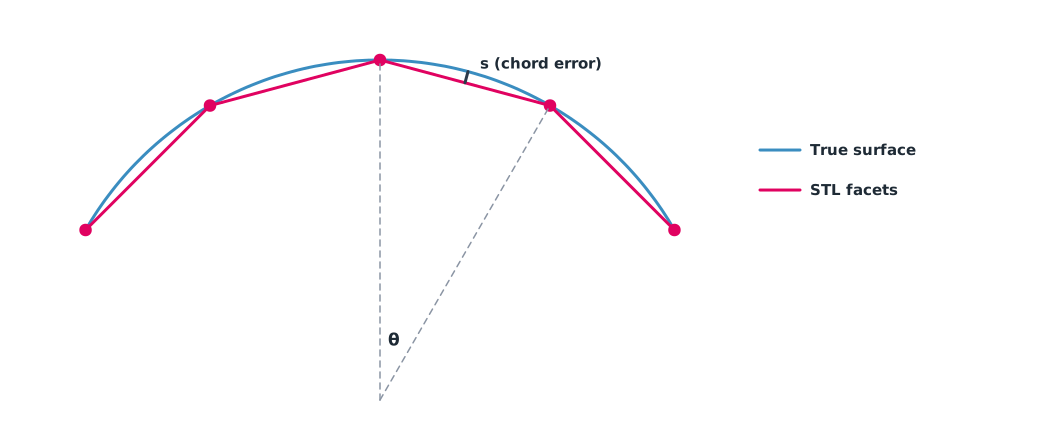
Example 2 A cylinder of radius 10 mm and height 20 mm
import math

R = 10.0
for s in (0.1, 0.05, 0.01):
    n = math.ceil(math.pi / math.acos(1 - s / R))
    triangles = 2 * n + 2 * (n - 2)            # side wall + top and bottom caps
    size = 84 + 50 * triangles
    print(f"chord error {s:4.2f} mm: {n:>3} segments, {triangles:>3} triangles, binary STL {size:,} bytes")
chord error 0.10 mm: 23 segments, 88 triangles, binary STL 4,484 bytes
chord error 0.05 mm: 32 segments, 124 triangles, binary STL 6,284 bytes
chord error 0.01 mm: 71 segments, 280 triangles, binary STL 14,084 bytesReducing the chord error from 0.1 to 0.01 mm roughly triples the segment count. An FDM printer with a 0.4 mm nozzle gains little from resolution far finer than the machine’s accuracy, so choose a value that suits the process.
Module lab
Lab: a parametric camera mount (L05)
- Create a parameter table in FreeCAD (or Onshape, OpenSCAD) for thickness, hole spacing and screw size, in mm.
- Draw a fully constrained sketch that refers to the table, then Pad and Pocket the mount holes.
- Change the spacing and screw as in Example 1, checking that the shape stays valid and meets the team rules.
- Export STEP, STL at three resolutions and 3MF, and compare file sizes with Example 2.
- Keep every CAD source version with a version number and date.
Common mistakes
Watch out
- Sketches not fully constrained, so shapes change by themselves.
- Keeping only STL and not the CAD source.
- Forgetting units when importing STL into a slicer, making the part too small or large.
- Setting chord error smaller than needed.
- Typing values into the sketch instead of referring to the parameter table.
Summary
- A fully constrained sketch has zero DOF and uses constraints that express design intent.
- A parameter table makes design changes fast and design rules checkable.
- CAD source keeps history, STEP exchanges geometry, and STL and 3MF are for printing.
- Smaller chord error means more triangles and larger files.
Check your understanding
- How many DOF does an unconstrained circle in a sketch have (centre and radius)?
- How big is a binary STL file with 1,000 triangles?
- Which format keeps feature history?
- A 10 mm radius circle uses 24 segments. What is the chord error?
- Why keep a STEP file even when you already have an STL?
Answers
- 3 DOF.
- bytes
- The program’s CAD source (such as .FCStd).
- mm
- STEP keeps exact curved surfaces, so it can be edited or passed to another CAD program; STL is only an approximation in triangles.
Key formulas
| Chord error of an arc | |
| Number of segments in a circle | |
| Binary STL file size |
Key references
- FreeCAD Project. Sketcher workbench. FreeCAD documentation. link
- FreeCAD Project. Mesh FromPartShape. FreeCAD documentation. link
- International Organization for Standardization. (2016). Industrial automation systems and integration — Product data representation and exchange — Part 21: Implementation methods: Clear text encoding of the exchange structure (ISO 10303-21:2016). link
- Burkardt, J. STLB: Binary STL files. Florida State University, Department of Scientific Computing. link
- 3MF Consortium. 3MF core specification (v1.4.0). link
- Giesecke, F. E., Lockhart, S., Goodman, M., & Johnson, C. M. (2023). Technical drawing with engineering graphics (16th ed.). Pearson. link
Further reading
Study the assigned knowledge units in advance, review media and take the module quiz
CAD and 3D printing for drone parts
Designing a parametric camera mount
FreeCAD
In class / field
Lab or field practice from worksheets with a safety checklist
Learning evidence: Checked worksheets and quiz results