Introductory strength analysis
UAT 208 Digital Drafting and Prototyping Technology
Lesson
By the end of this module you will be able to
- Compute the deflection and bending stress of a cantilever with a tip load
- Compare the second moments of area of different sections
- Explain the anisotropy of FDM parts and choose a print direction to suit the load
- Compute safety factors and use FEM with awareness of its limits
Why this matters
A drone arm carries the motor’s thrust at its tip. Too flexible and it bends and vibrates; too weak and it snaps in the air. A quick calculation before printing rules out designs that will not survive and shows where to add thickness. The drone knowledge base’s design and integration unit and lab L04 use the drone arm as the same problem.
Cantilevers
An arm fixed at the body at one end and loaded at the tip is a cantilever. Standard results from mechanics of materials (Hibbeler, 2023) give the tip deflection and the maximum bending stress at the root , where is the material modulus, is the section’s second moment of area and is the distance from the neutral axis to the surface.
The formulas say two important things. Deflection goes with , so doubling the arm length gives eight times the deflection. And for a rectangle , so the height in the load direction matters far more than the width: turning the same section on edge makes it several times stiffer without adding mass.
Anisotropy of printed parts
FDM parts are built layer by layer, and the bond between layers is weaker than the material within a layer. The Prusament PLA datasheet gives printed specimens a yield strength of about 51 MPa and a modulus of 2.3 GPa, but interlayer adhesion of only about 17 MPa. Ahn et al. (2002), working with ABS, found that raster direction within a layer changes tensile strength a great deal, and recommended orienting parts so that tensile loads run along the strands.
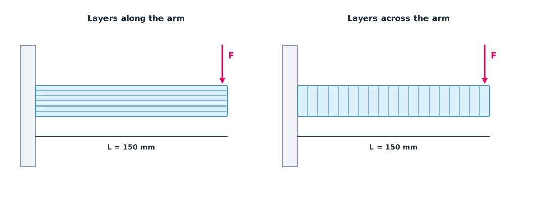
Example 1 A 150 mm PLA arm with a 10 N load
Using the printed modulus of 2.3 GPa and comparing in-layer strength 51 MPa with interlayer 17 MPa.
E, F, L = 2300.0, 10.0, 150.0                 # MPa, N, mm
STRENGTH_ALONG, STRENGTH_ACROSS = 51.0, 17.0  # MPa per the Prusament PLA datasheet

for b, h in ((20, 10), (10, 20), (15, 15)):
    inertia = b * h ** 3 / 12
    deflection = F * L ** 3 / (3 * E * inertia)
    stress = F * L * (h / 2) / inertia
    print(f"section {b}x{h} mm (h in load direction): deflection {deflection:5.2f} mm, stress {stress:4.1f} MPa, "
          f"SF along layers {STRENGTH_ALONG / stress:5.1f}, across layers {STRENGTH_ACROSS / stress:4.1f}")
section 20x10 mm (h in load direction): deflection 2.93 mm, stress 4.5 MPa, SF along layers 11.3, across layers 3.8
section 10x20 mm (h in load direction): deflection 0.73 mm, stress 2.2 MPa, SF along layers 22.7, across layers 7.6
section 15x15 mm (h in load direction): deflection 1.16 mm, stress 2.7 MPa, SF along layers 19.1, across layers 6.4The same 200 mm² section turned with its tall side along the load deflects four times less. The safety factor is enough in every case for a static load, but printing so the layers run across the arm cuts it by about three times, and real drone loads include impacts and vibration far above the static load.
What thickness buys
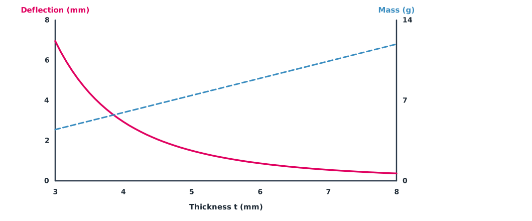
Example 2 Sweeping the thickness of a mounting plate
A plate 20 mm wide and 60 mm long, fixed at one end with 10 N at the other (lab L04 changes thickness only).
E, F, L, B, RHO = 2300.0, 10.0, 60.0, 20.0, 1.24e-3     # MPa, N, mm, mm, g/mm³

for t in (3, 4, 5, 6, 8):
    inertia = B * t ** 3 / 12
    deflection = F * L ** 3 / (3 * E * inertia)
    mass = B * t * L * RHO
    print(f"t = {t} mm: deflection {deflection:6.3f} mm, mass {mass:5.2f} g")
t = 3 mm: deflection 6.957 mm, mass 4.46 g
t = 4 mm: deflection 2.935 mm, mass 5.95 g
t = 5 mm: deflection 1.503 mm, mass 7.44 g
t = 6 mm: deflection 0.870 mm, mass 8.93 g
t = 8 mm: deflection 0.367 mm, mass 11.90 gGoing from 3 to 6 mm doubles the mass but cuts deflection eightfold, so thickness is the most effective variable, though each further increase gains less.
FEM, used wisely
Real shapes are more complex than a straight beam, so FEM (finite element method) tools such as FreeCAD’s FEM workbench, with CalculiX as the default solver, are used. But results are only as good as the inputs: material, loads and supports must match reality, the mesh should be refined until results stop changing much, and simple cases should be checked against beam formulas first. Most standard FEM treats the material as isotropic, so it does not see the weak interlayer bonds of printed parts.
Module lab
Lab: thickness and arm deflection (L04)
- Build a simple arm in CAD, clearly defining material, load and support.
- Run a static analysis with FreeCAD FEM and compare deflection with the code from Example 2.
- Change thickness only, recording deflection and mass.
- Refine the mesh two levels and see how much the results change.
- Print the arm in two orientations, load it with weights and measure deflection against the calculation.
Common mistakes
Watch out
- Using filament strength instead of printed-part values.
- Ignoring layer direction.
- Orienting the section the wrong way for the load.
- Trusting FEM without checking mesh and supports.
- Designing for static loads only, forgetting impacts and vibration.
Summary
- For a cantilever and ; deflection is very sensitive to length and section height.
- Putting the section’s tall side along the load adds stiffness without adding mass.
- FDM parts are weak across layer bonds (PLA about 17 MPa versus 51 MPa).
- FEM needs correct conditions, a mesh check and comparison with formulas for simple cases.
Check your understanding
- An arm grows from 100 to 200 mm. By what factor does deflection change?
- A 10×20 mm section with the 20 mm side along the load has what I?
- What is the safety factor for 5 MPa stress in a part of 17 MPa strength?
- Why use printed-part strength rather than filament strength?
- What is I for a round tube of 12 mm outer and 10 mm inner diameter?
Answers
- times.
- mm⁴
- Printed parts have voids and bonds between strands and layers, so their real strength is below that of the filament.
- mm⁴
Key formulas
| Cantilever deflection | |
| Maximum bending stress | |
| Second moment of area |
Key references
- Hibbeler, R. C. (2023). Mechanics of materials (11th ed.). Pearson. link
- Prusa Polymers. (2022). Technical datasheet: Prusament PLA (Version 1.1). link
- Prusa Polymers. (2022). Technical datasheet: Prusament PETG (Version 1.1). link
- Ahn, S.-H., Montero, M., Odell, D., Roundy, S., & Wright, P. K. (2002). Anisotropic material properties of fused deposition modeling ABS. Rapid Prototyping Journal, 8(4), 248–257. link
- FreeCAD Project. FEM workbench. FreeCAD documentation. link
Further reading
Study the assigned knowledge units in advance, review media and take the module quiz
In class / field
Lab or field practice from worksheets with a safety checklist
Learning evidence: Checked worksheets and quiz results