Prototyping and testing
UAT 208 Digital Drafting and Prototyping Technology
Lesson
By the end of this module you will be able to
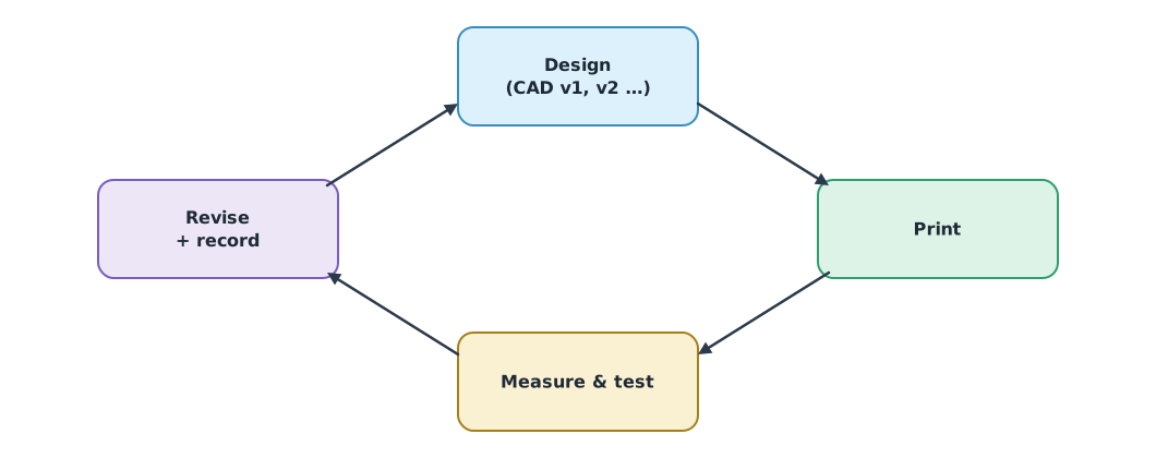
- Run the design, print, measure-and-test, revise cycle systematically, recording each version
- Measure printed hole sizes, relate them to design sizes and compute compensation
- Analyse load-to-failure tests and compute safety factors
- Link part test results to the drone's mass budget and system integration
Why this matters
A first prototype is almost never entirely right: holes are small, a bracket cracks at a corner. The value of a prototype lies in what you learn from measuring and testing it and feed back into the design. 3D printing makes this cycle fast, but it only works if every version is recorded and one factor is changed at a time. The drone knowledge base’s design and integration unit reminds us to connect parts to the whole, such as the mass budget and the cables that tend to be forgotten.
Measure, then compensate hole sizes
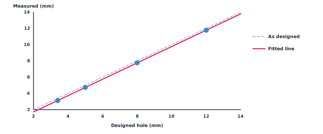
FDM holes usually come out smaller than designed, because extruded plastic spreads and the surface is faceted. A reliable approach is to print a test piece with several hole sizes, measure with pin gauges or calipers, and find the relationship. If the error is constant, a slicer compensation such as PrusaSlicer’s XY size compensation can be used, though it also affects outer walls; alternatively, change hole sizes only in CAD.
Example 1 Hole compensation from a test piece
Mean hole sizes measured on three pieces per size (hypothetical values).
import statistics as st

design = [3.4, 5.0, 8.0, 12.0]            # mm
measured = [3.12, 4.74, 7.76, 11.78]      # mm

mx, my = st.mean(design), st.mean(measured)
a = sum((x - mx) * (y - my) for x, y in zip(design, measured)) / sum((x - mx) ** 2 for x in design)
b = my - a * mx
print(f"measured = {a:.4f} x design {b:+.3f} mm")
for d, m in zip(design, measured):
    print(f"design {d:>4} mm -> measured {m:5.2f} mm (error {m - d:+.2f} mm, fit residual {m - (a * d + b):+.3f})")
for target in (3.4, 8.0):
    print(f"to get {target} mm, draw the hole at {(target - b) / a:.2f} mm")
measured = 1.0067 x design -0.298 mm
design 3.4 mm -> measured 3.12 mm (error -0.28 mm, fit residual -0.005)
design 5.0 mm -> measured 4.74 mm (error -0.26 mm, fit residual +0.004)
design 8.0 mm -> measured 7.76 mm (error -0.24 mm, fit residual +0.004)
design 12.0 mm -> measured 11.78 mm (error -0.22 mm, fit residual -0.003)
to get 3.4 mm, draw the hole at 3.67 mm
to get 8.0 mm, draw the hole at 8.24 mmA slope near 1 means holes shrink by almost the same amount at every size, about 0.2–0.3 mm, with small holes shrinking slightly more. Enlarging holes in CAD using this equation is more accurate than a single compensation value. It applies only to that printer, material and set of settings.
Load-to-failure testing
The calculations in Module 3 are estimates; real printed parts have voids, bonds and printing deviations, so several real parts must be tested, and a conservative value such as the minimum, or the mean minus two standard deviations, compared with the required load.
Example 2 Is the camera mount strong enough?
The camera weighs 0.3 kg. The team requires the mount to survive an impact of 20 times its weight in a hard landing (about 60 N) with a safety factor of at least 2.0. Results for five pieces (hypothetical values):
import statistics as st

failure_n = [182, 175, 190, 168, 186]     # N load at which the mount failed
M_KG, G, SHOCK, SF_REQUIRED = 0.3, 9.80665, 20, 2.0

required = M_KG * G * SHOCK
mean, sd = st.mean(failure_n), st.stdev(failure_n)
conservative = min(min(failure_n), mean - 2 * sd)
sf = conservative / required
print(f"required load {required:.1f} N")
print(f"failure loads: mean {mean:.1f} N, sd {sd:.1f} N, minimum {min(failure_n)} N, mean - 2sd {mean - 2 * sd:.1f} N")
print(f"safety factor on the conservative value {sf:.2f} -> {'PASS' if sf >= SF_REQUIRED else 'FAIL'}")
required load 58.8 N
failure loads: mean 180.2 N, sd 8.8 N, minimum 168 N, mean - 2sd 162.6 N
safety factor on the conservative value 2.76 -> PASSIt passes, but five pieces is still a small sample and the test was a single static load. Vibration and temperature tests are needed too, because PLA softens at modest temperatures (HDT about 55 °C in the datasheet). In the Thai sun, dark parts on the airframe may approach that level, so measure the real temperature.
Versioning and integration
Every prototype version should have a version number, date, CAD source, 3MF file, print settings, material and test results. Once a part passes, put its real mass into the drone’s mass budget and check assembly, such as screw head clearance, camera cables and space to disassemble, since, as the knowledge base unit stresses, parts that do not clash in CAD are not necessarily easy to assemble.
Module lab
Lab: a full camera mount prototype cycle
- Print a hole test piece with four sizes, three pieces per size, measure them and use the code from Example 1 to find the compensation.
- Update the camera mount CAD accordingly, print the new version and check that the screws fit.
- Load at least five pieces to failure with safe equipment and analyse them with Example 2.
- Fit the mount to the drone, weigh it and record it in the mass budget.
- Write a version-by-version report stating what changed and what resulted.
Common mistakes
Watch out
- Changing several things at once between versions.
- Not recording print settings and material.
- Using compensation values from another printer.
- Testing one piece and drawing conclusions.
- Forgetting the material’s service temperature.
Summary
- The design, print, measure-and-test, revise cycle works when every version is recorded and one factor changes at a time.
- Compensate holes using a regression of measured sizes, valid only for that printer and settings.
- Use a conservative value from several test pieces to compute the safety factor.
- Feed part results back into the whole system’s mass budget and assembly.
Check your understanding
- If measured = design − 0.3 mm, what hole should be drawn to get 3.4 mm?
- The required load is 50 N and the minimum failure load is 140 N. What is the safety factor?
- Mean failure load 150 N, standard deviation 10 N: what is the mean minus two standard deviations?
- What does PrusaSlicer’s XY size compensation affect?
- Why test temperature for PLA parts on drones in Thailand?
Answers
- 3.7 mm.
- N
- Both holes and outer walls in X and Y.
- PLA has an HDT of about 55 °C; in the sun the airframe may get hot enough to soften and deform the part.
Key formulas
| Line of printed size | |
| Design size needed for a target | |
| Safety factor |
Key references
- Gibson, I., Rosen, D., Stucker, B., & Khorasani, M. (2021). Additive manufacturing technologies (3rd ed.). Springer. link
- International Organization for Standardization. (1989). General tolerances — Part 1: Tolerances for linear and angular dimensions without individual tolerance indications (ISO 2768-1:1989). link
- International Organization for Standardization. (1979). Fasteners — Clearance holes for bolts and screws (ISO 273:1979). link
- Prusa Polymers. (2022). Technical datasheet: Prusament PLA (Version 1.1). link
- Hibbeler, R. C. (2023). Mechanics of materials (11th ed.). Pearson. link
Further reading
Study the assigned knowledge units in advance, review media and take the module quiz
In class / field
Lab or field practice from worksheets with a safety checklist
Learning evidence: Checked worksheets and quiz results