3D printing and slicers
UAT 208 Digital Drafting and Prototyping Technology
Lesson
By the end of this module you will be able to
- Explain additive manufacturing processes under ISO/ASTM 52900 and where FDM fits
- Explain the role of perimeters, infill and supports in slicer settings
- Estimate mass, filament length and print time from part volume
- Choose part orientation by weighing print time, surface, supports and load direction
Why this matters
3D printing produces prototype parts within hours, but the settings in the slicer, which turns an STL into machine instructions, decide strength, surface, time and material. Poor choices give parts that snap along layers, take longer than needed or waste material. Lab L06 in the drone knowledge base compares settings in PrusaSlicer before printing.
Additive manufacturing processes
ISO/ASTM 52900:2021 divides additive manufacturing into seven categories: binder jetting, directed energy deposition, material extrusion, material jetting, powder bed fusion, sheet lamination and vat photopolymerization. The lab’s FDM printers belong to material extrusion (MEX), dispensing material through a nozzle line by line. Gibson et al. (2021) explain the strengths and limits of each category.
Perimeters, infill and supports
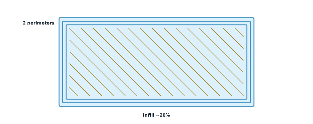
- Perimeters (walls): the outer lines of each layer. The PrusaSlicer guide says a model’s strength is mostly defined by the number of perimeters, not the infill.
- Infill: the internal structure that supports the top layers, set as a percentage of the interior.
- Supports: temporary structures under overhangs, which must be removed and leave marks on the surface.
Example 1 Estimating mass and filament length
The CAD camera mount has a volume of 4.2 cm³ and a surface area of 30 cm², printed with 2 perimeters, 0.45 mm line width, 20% infill and 1.75 mm PLA of density 1.24 g/cm³ (Prusament PLA datasheet). This is a simple estimate; the slicer computes it more accurately.
import math

V_CM3, AREA_CM2 = 4.2, 30.0
PERIMETERS, LINE_W_MM, INFILL = 2, 0.45, 0.20
RHO, D_MM = 1.24, 1.75                                  # g/cm³, mm

shell = min(V_CM3, AREA_CM2 * PERIMETERS * LINE_W_MM / 10)
material = shell + INFILL * (V_CM3 - shell)
mass = RHO * material
cm_per_gram = 1 / (RHO * math.pi * (D_MM / 20) ** 2)
print(f"shell {shell:.2f} cm³ + infill {INFILL:.0%} of core -> {material:.2f} cm³")
print(f"mass {mass:.2f} g, filament {mass * cm_per_gram / 100:.2f} m ({cm_per_gram:.1f} cm per gram)")
for inf in (0.1, 0.4, 1.0):
    print(f"infill {inf:.0%}: mass {RHO * (shell + inf * (V_CM3 - shell)):.2f} g")
shell 2.70 cm³ + infill 20% of core -> 3.00 cm³
mass 3.72 g, filament 1.25 m (33.5 cm per gram)
infill 10%: mass 3.53 g
infill 40%: mass 4.09 g
infill 100%: mass 5.21 gIn a small part like this most of the material is in the walls, so raising infill from 20% to 40% adds only about 10% mass; adding perimeters usually buys strength more efficiently.
Part orientation
How the part sits on the bed sets the layer count, print time, need for supports and surface finish, and above all the direction of layer bonds relative to the load (Module 3).
Example 2 Flat or upright
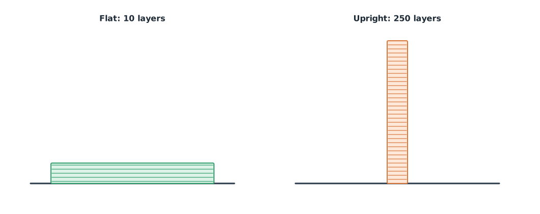
A 50 × 20 × 2 mm mounting plate with 0.2 mm layers, an average flow of 8 mm³/s and 1.5 s per layer change (hypothetical values).
SIZE = (50.0, 20.0, 2.0)                 # mm
LAYER, FLOW, CHANGE_S = 0.2, 8.0, 1.5     # mm, mm³/s, s per layer
volume = SIZE[0] * SIZE[1] * SIZE[2]

for name, height in (("flat", SIZE[2]), ("on edge", SIZE[1]), ("upright", SIZE[0])):
    layers = round(height / LAYER)
    minutes = (volume / FLOW + layers * CHANGE_S) / 60
    print(f"{name:<8}: {layers:>3} layers, about {minutes:4.1f} min")
flat : 10 layers, about 4.4 min
on edge : 100 layers, about 6.7 min
upright : 250 layers, about 10.4 minPrinting upright takes about two and a half times as long as flat, because there are more layers. A tall thin part also wobbles during printing, and if the plate is bent in use, the layer bonds sit in the weak direction. Flat is better for both time and strength for this part.
Module lab
Lab: reading the slicer (L06)
- Import the STL or 3MF from Module 2 into PrusaSlicer, choose the real printer and material profiles, and record the software version.
- Slice with two orientations and inspect the layer preview and supports.
- Change perimeters and infill one at a time, recording the time and mass the slicer computes.
- Compare with the estimates in Examples 1 and 2 and explain the differences.
- Save the 3MF project with all settings.
Common mistakes
Watch out
- Raising infill for strength when perimeters work better.
- Orienting parts so layer bonds carry tension.
- Using printer or material profiles that do not match reality.
- Not checking the layer preview before printing.
- Treating the preview as a strength test.
Summary
- FDM belongs to material extrusion among the seven ISO/ASTM 52900 categories.
- Perimeters matter more for strength than infill; supports help overhangs but leave marks.
- Mass can be estimated from shell plus interior, and 1.75 mm filament runs about 33.5 cm per gram.
- Orientation sets layer count, time, supports and the direction of layer bonds relative to the load.
Check your understanding
- Which ISO/ASTM 52900 category do FDM printers belong to?
- How many layers does a 30 mm tall part with 0.2 mm layers have?
- About how long is 50 g of 1.75 mm PLA filament?
- According to the PrusaSlicer guide, which setting matters more for strength?
- Why should a thin mounting plate not be printed upright?
Answers
- Material extrusion (MEX).
- 150 layers.
- cm, about 16.8 m.
- The number of perimeters.
- It takes longer because of many layers, the part wobbles, and the layer bonds end up in the direction that carries bending.
Key formulas
| Approximate material volume | |
| Filament length per mass | |
| Layer count |
Key references
- International Organization for Standardization & ASTM International. (2021). Additive manufacturing — General principles — Fundamentals and vocabulary (ISO/ASTM 52900:2021). link
- Gibson, I., Rosen, D., Stucker, B., & Khorasani, M. (2021). Additive manufacturing technologies (3rd ed.). Springer. link
- Prusa Research. Layers and perimeters. Prusa knowledge base. link
- Prusa Research. Infill. Prusa knowledge base. link
- Prusa Polymers. (2022). Technical datasheet: Prusament PLA (Version 1.1). link
Further reading
Study the assigned knowledge units in advance, review media and take the module quiz
In class / field
Lab or field practice from worksheets with a safety checklist
Learning evidence: Checked worksheets and quiz results