GCS and communications
UAT 301 Unmanned Aircraft Systems Technology
Lesson
By the end of this module you will be able to
- Explain the functions and architecture of a ground control station (GCS), C2 link and payload link
- Explain the STANAG 4586 levels of interoperability for GCS
- Read a QGroundControl .plan mission file and check distance, time and altitude with a program
- Compute the radio horizon and the altitude needed to keep radio line of sight
Why this matters
The pilot does not sit in the aircraft. Everything they know and command passes through the ground control station (GCS) and radio links. If the GCS shows wrong information or the mission plan is wrong, a perfectly healthy drone can still fly the wrong way. UAT 207 covered radio waves, MAVLink and failsafes. This module looks at system level: what a GCS consists of, how to check a mission plan before uploading it, and how far a link can reach.
GCS architecture
The main functions of a GCS are mission planning, commanding and monitoring the aircraft through the C2 link (command and control), displaying and recording payload data through the payload link, and distributing data to users (Fahlstrom and colleagues). The C2 link needs a low data rate but very high reliability; the video link needs a high data rate but tolerates some loss. Small systems may carry both links on one radio, but C2 data must always take priority.
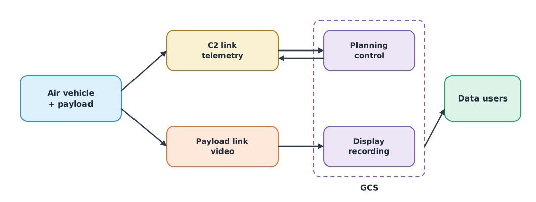
NATO STANAG 4586 defines standard interfaces between a GCS and aircraft from different makers and divides levels of interoperability (LOI) into five (Serrano, NATO STO): level 1, indirect receipt or transmission of payload data and metadata; level 2, direct receipt or transmission without control of the aircraft; level 3, control and monitoring of the payload; level 4, control and monitoring of the aircraft excluding launch and recovery; and level 5, control of the aircraft including launch and recovery. The idea applies to civil systems too: before buying, ask whether the GCS uses an open protocol such as MAVLink that QGroundControl can read, or is tied to one maker’s software.
Checking the mission plan before upload
QGroundControl saves missions as .plan files in JSON. Inside, mission.items lists items, each with a command from the MAVLink command set, for example 16 for flying to a waypoint (MAV_CMD_NAV_WAYPOINT), 22 for take-off (MAV_CMD_NAV_TAKEOFF) and 20 for return to launch (MAV_CMD_NAV_RETURN_TO_LAUNCH), and seven params, the last three of which are latitude, longitude and altitude. The drone knowledge base’s QGroundControl unit demonstrates connecting to SITL, placing waypoints and exporting a mission file.
Example 1 Checking a .plan file with a program
A VTOL flood survey mission at 16 m/s (hypothetical coordinates). The program computes each leg, the flight time and the farthest distance from home, and checks altitude against the 90 m ceiling used for general flights under the CAAT rules.
import math

plan = {"fileType": "Plan", "version": 1, "groundStation": "QGroundControl",
        "mission": {"version": 2, "cruiseSpeed": 16, "plannedHomePosition": [14.0340, 100.6120, 5.0],
                    "items": [
                        {"type": "SimpleItem", "command": 22, "frame": 3, "params": [0, 0, 0, None, 14.0340, 100.6120, 40]},
                        {"type": "SimpleItem", "command": 16, "frame": 3, "params": [0, 0, 0, None, 14.0450, 100.6200, 90]},
                        {"type": "SimpleItem", "command": 16, "frame": 3, "params": [0, 0, 0, None, 14.0450, 100.6400, 90]},
                        {"type": "SimpleItem", "command": 16, "frame": 3, "params": [0, 0, 0, None, 14.0410, 100.6400, 90]},
                        {"type": "SimpleItem", "command": 16, "frame": 3, "params": [0, 0, 0, None, 14.0410, 100.6200, 120]},
                        {"type": "SimpleItem", "command": 20, "frame": 2, "params": [0, 0, 0, 0, 0, 0, 0]},
                    ]}}
MAX_ALT = 90                                   # m above home (frame 3)

def haversine(lat1, lon1, lat2, lon2, r=6_371_000):
    p1, p2 = math.radians(lat1), math.radians(lat2)
    dp, dl = p2 - p1, math.radians(lon2 - lon1)
    h = math.sin(dp / 2) ** 2 + math.cos(p1) * math.cos(p2) * math.sin(dl / 2) ** 2
    return 2 * r * math.asin(math.sqrt(h))

m = plan["mission"]
home = m["plannedHomePosition"][:2]
points, problems = [home], []
for i, it in enumerate(m["items"], 1):
    if it["command"] in (16, 22):
        lat, lon, alt = it["params"][4:7]
        points.append([lat, lon])
        if alt > MAX_ALT:
            problems.append(f"item {i}: altitude {alt} m > {MAX_ALT} m")
if m["items"][-1]["command"] != 20:
    problems.append("mission does not end with RETURN_TO_LAUNCH")
points.append(home)
legs = [haversine(*points[k], *points[k + 1]) for k in range(len(points) - 1)]
far = max(haversine(*home, *p) for p in points)
print("legs (m):", [round(x) for x in legs])
print(f"total {sum(legs) / 1000:.2f} km, {sum(legs) / m['cruiseSpeed'] / 60:.1f} min at {m['cruiseSpeed']} m/s, farthest {far / 1000:.2f} km from home")
print("problems:", problems or "none")
legs (m): [0, 1497, 2157, 445, 2157, 1162]
total 7.42 km, 7.7 min at 16 m/s, farthest 3.26 km from home
problems: ['item 5: altitude 120 m > 90 m']The program finds a waypoint above the ceiling, which is easy to miss on the map screen. Checking every mission file with a program before upload is therefore a cheap and effective safety gate. The computed flight time excludes turns, climbs, descents and wind, so add margin.
How far can the link reach?
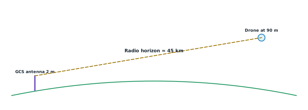
Besides transmit power and receiver sensitivity (the link budget in UAT 207), links at VHF and above are limited by the Earth’s curvature. Radio waves bend slightly in the atmosphere, so the Earth is treated as if its radius were times larger (ITU-R P.834). The radio horizon between antennas at and metres is about km. In practice, trees, buildings and terrain usually block the path before the horizon, and the Fresnel zone must also be kept clear.
Example 2 Radio horizon and minimum altitude
import math

def radio_horizon_km(h1, h2):
    return 4.12 * (math.sqrt(h1) + math.sqrt(h2))

def min_drone_alt(d_km, h_gcs):
    x = d_km / 4.12 - math.sqrt(h_gcs)
    return max(0.0, x) ** 2

print(f"GCS 2 m, drone 90 m: horizon {radio_horizon_km(2, 90):.1f} km")
print(f"GCS 10 m mast, drone 90 m: horizon {radio_horizon_km(10, 90):.1f} km")
for d in (5, 20, 40):
    print(f"to keep radio line of sight at {d:>2} km with a 2 m antenna the drone must be above {min_drone_alt(d, 2):.1f} m")
GCS 2 m, drone 90 m: horizon 44.9 km
GCS 10 m mast, drone 90 m: horizon 52.1 km
to keep radio line of sight at 5 km with a 2 m antenna the drone must be above 0.0 m
to keep radio line of sight at 20 km with a 2 m antenna the drone must be above 11.8 m
to keep radio line of sight at 40 km with a 2 m antenna the drone must be above 68.8 mThe mapping area in this case is less than 4 km away, so the radio horizon is not a constraint. But searching 40 km away would need a height of almost 70 m just to clear the Earth’s curvature, before counting obstacles, and would be a beyond-visual-line-of-sight flight needing specific permission.
Module lab
Lab: plan and check a mission in SITL
- Start ArduPilot or PX4 SITL, connect QGroundControl, and check that telemetry is complete and the system time is correct
- Plan a survey of an area on campus with the Survey pattern and save it as a .plan file
- Adapt Example 1 to read the real file with
json.loadand check altitude, farthest distance and the last command - Fly the mission in SITL, compare the real time with the computed time, and explain the difference
- Compute the radio horizon for the chosen GCS site and list obstacles that might block the link
Common mistakes
Watch out
- Uploading a mission without checking altitude and the last command
- Confusing altitude frames between above home and above sea level
- Letting video take bandwidth from C2
- Assuming the link reaches the radio horizon without looking at obstacles
- Tying the system to closed GCS software without assessing the long-term effect
Summary
- The GCS plans, commands, displays, records and distributes data through a C2 link and a payload link with different needs
- STANAG 4586 defines five levels of GCS interoperability and promotes standard interfaces
- A .plan file is JSON that can be checked by a program before every upload
- Radio horizon ≈ 4.12(√h₁ + √h₂) km, but obstacles usually limit the link first
Check your understanding
- How do the needs of the C2 link and the video link differ?
- In a .plan file, what do commands 16 and 20 mean?
- With a 4 m antenna and a drone at 100 m, what is the approximate radio horizon?
- Why check the mission file with a program even after looking at it on the map?
- If a drone must fly 30 km from a GCS with a 2 m antenna, how high must it fly at least to clear the Earth’s curvature?
Answers
- C2 has a low data rate but needs very high reliability; video has a high data rate but tolerates some loss
- 16 flies to a waypoint; 20 returns to launch
- km
- Altitude above the ceiling, a wrong frame or a missing last command are easy to miss on screen
- m
Key formulas
| Great-circle distance (haversine) | |
| Radio horizon (k = 4/3) |
Key references
- QGroundControl. QGroundControl user guide. link
- QGroundControl Dev Team. Plan file format. QGroundControl developer guide. link
- MAVLink Development Team. MAVLink common message set (common.xml). link
- Serrano, D. (2015). Key initiatives for interoperability through standardization: Applicability to small unmanned vehicles (STO-EN-SCI-271). NATO Science and Technology Organization. link
- International Telecommunication Union. (2017). Effects of tropospheric refraction on radiowave propagation (Recommendation ITU-R P.834-9). link
- International Telecommunication Union. (1994). Definitions of terms relating to propagation in non-ionized media (Recommendation ITU-R P.310-9). link
- Fahlstrom, P. G., Gleason, T. J., & Sadraey, M. H. (2022). Introduction to UAV systems (5th ed.). Wiley. link
- สำนักงานการบินพลเรือนแห่งประเทศไทย. (2569). ประกาศ กพท. เรื่อง หลักเกณฑ์และวิธีการในการอนุญาตให้ผู้บังคับหรือปล่อยอากาศยานซึ่งไม่มีนักบิน ประเภทอากาศยานที่ควบคุมการบินจากภายนอก ที่มีน้ำหนักไม่เกิน 25 กิโลกรัม ปฏิบัติแตกต่างไปจากเงื่อนไขที่กำหนด พ.ศ. 2569 (มีผล 17 พฤษภาคม 2569). link
Further reading
Study the assigned knowledge units in advance, review media and take the module quiz
In class / field
Lab or field practice from worksheets with a safety checklist
Learning evidence: Checked worksheets and quiz results