Payloads and mission data
UAT 301 Unmanned Aircraft Systems Technology
Lesson
By the end of this module you will be able to
- Compute a camera's instantaneous field of view (IFOV) and ground sample distance
- Estimate detection, recognition and identification ranges with the Johnson criteria
- Compute blur from gimbal motion and aircraft movement
- Choose payloads and imaging settings that answer the mission's question
Why this matters
The aircraft is only a carrier; the mission’s results come from the payload. The night search in this case needs a thermal camera, and users will ask “how far away can it see a person?” Sellers often answer with a single number. An engineer must be able to compute it and know the assumptions behind it. The drone knowledge base’s payload unit recommends choosing sensors from the required output and understanding calibration, ground sample distance and the accuracy of processed results.
Field of view per pixel
Each camera pixel sees a small angle called the IFOV (instantaneous field of view), equal to the pixel size divided by the focal length . Looking down from height , the ground area per pixel (GSD) is . The examples in this module use the real specification of the thermal camera in the DJI Zenmuse H20T: 640×512 pixels, 12 µm pixel pitch, 13.5 mm focal length, and a gimbal angular vibration range of ±0.01°, as listed on the manufacturer’s specification page. This gives an IFOV of about 0.889 mrad.
The Johnson criteria
Johnson (1958) tested how many line pairs (cycles) of detail across a target are needed to perform each task with 50% probability. The widely used values are 1.0 line pair for detection (knowing an object is there), 4.0 for recognition (knowing it is a person or a vehicle) and 6.4 for identification (telling who or which model) (Perić and colleagues, 2019). One line pair takes two pixels. The critical dimension of a standard 1.8 m × 0.5 m person is m, and of a vehicle 2.3 m.
Example 1 How far can the thermal camera see a person?
import math

PITCH, FOCAL = 12e-6, 13.5e-3                   # m, pixel pitch and focal length
IFOV = PITCH / FOCAL                            # rad
JOHNSON = {"detection": 1.0, "recognition": 4.0, "identification": 6.4}   # line pairs
TARGETS = {"person": math.sqrt(1.8 * 0.5), "vehicle": 2.3}               # m, critical dimension

print(f"IFOV {IFOV * 1000:.3f} mrad, GSD at 90 m {90 * IFOV * 100:.1f} cm")
for name, dc in TARGETS.items():
    ranges = {k: dc / (2 * n * IFOV) for k, n in JOHNSON.items()}
    print(f"{name:<8} (Dc {dc:.2f} m): " + ", ".join(f"{k} {r:,.0f} m" for k, r in ranges.items()))
IFOV 0.889 mrad, GSD at 90 m 8.0 cm
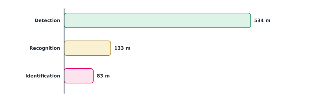
person (Dc 0.95 m): detection 534 m, recognition 133 m, identification 83 m
vehicle (Dc 2.30 m): detection 1,294 m, recognition 323 m, identification 202 mThese ranges are geometric limits only. They do not include the temperature difference between a person and the background, humidity, rain or the camera’s sensitivity. Perić and colleagues (2019) compared predictions with field measurements and found that real ranges depend strongly on these conditions. In a night flood, water surfaces and wet people may have similar temperatures, so the real range can be shorter than these numbers. The team must test in the field with real targets before setting the search altitude.
Gimbal and blur
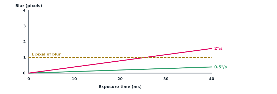
During the exposure, if the camera rotates at angular rate , the image moves by , or pixels. If the aircraft moves at speed , the ground image moves by pixels. Blur above about 1 pixel destroys the detail that the Johnson calculation assumes. The gimbal reduces camera rotation caused by aircraft vibration and tilting.
Example 2 Blur from the gimbal and from flight
import math

IFOV = 12e-6 / 13.5e-3                          # rad
IFOV_DEG = math.degrees(IFOV)
print(f"gimbal vibration 0.01 deg = {0.01 / IFOV_DEG:.2f} pixel")
for rate in (0.5, 2.0):                         # deg/s of residual rotation after the gimbal
    for ms in (10, 20, 40):
        print(f"rate {rate} deg/s, exposure {ms} ms: {rate * ms / 1000 / IFOV_DEG:.2f} px")
    print(f"  longest exposure for 1 px at {rate} deg/s: {IFOV_DEG / rate * 1000:.0f} ms")

H, V = 90, 16                                   # height m, speed m/s
gsd = H * IFOV
for ms in (5, 10):
    print(f"forward motion at {V} m/s, {H} m, {ms} ms: {V * ms / 1000 / gsd:.1f} px")
gimbal vibration 0.01 deg = 0.20 pixel
rate 0.5 deg/s, exposure 10 ms: 0.10 px
rate 0.5 deg/s, exposure 20 ms: 0.20 px
rate 0.5 deg/s, exposure 40 ms: 0.39 px
longest exposure for 1 px at 0.5 deg/s: 102 ms
rate 2.0 deg/s, exposure 10 ms: 0.39 px
rate 2.0 deg/s, exposure 20 ms: 0.79 px
rate 2.0 deg/s, exposure 40 ms: 1.57 px
longest exposure for 1 px at 2.0 deg/s: 25 ms
forward motion at 16 m/s, 90 m, 5 ms: 1.0 px
forward motion at 16 m/s, 90 m, 10 ms: 2.0 pxThe vibration the gimbal allows is only 0.2 pixel, so it is not a problem. But if the aircraft turns or is hit by a gust so that the camera rotates at 2°/s, blur exceeds 1 pixel for exposures longer than about 25 ms. Flying forward at 16 m/s at 90 m blurs the image by 1–2 pixels at 5–10 ms exposures, so search flights should slow down or climb over areas that need detail.
Choosing a payload to fit the question
Fahlstrom and colleagues and Barnhart and colleagues recommend starting from the user’s question and then choosing the payload. “Where are people trapped?” needs a thermal camera plus a zoom camera to confirm. “How wide is the flood?” needs a mapping camera with accurate positions. “How far has the water dropped?” may need a height model from photogrammetry or LiDAR. Every image needs a correct time and position, or users will place things in the wrong location, as covered in UAT 311.
Module lab
Lab: field check of camera performance
- Read the specification of the programme’s camera and compute IFOV and GSD at the planned height
- Compute detection, recognition and identification ranges for a person with Example 1
- Have classmates stand at different distances in an open field, fly under the instructor’s supervision, and record the range at which viewers can actually perform each task
- Take images at different flight speeds and measure blur against Example 2
- Write a recommendation for search height and speed with reasons
Common mistakes
Watch out
- Trusting brochure detection ranges without asking which target and conditions they assume
- Forgetting that one line pair is two pixels
- Using geometric ranges without field testing
- Flying too fast so that images blur
- Choosing a payload before knowing the user’s question
Summary
- IFOV = pixel size / focal length, and GSD = height × IFOV
- The Johnson criteria use 1.0, 4.0 and 6.4 line pairs across the critical dimension for detection, recognition and identification
- Blur comes from camera rotation and aircraft motion and should stay below about 1 pixel
- Computed ranges are geometric limits and must be confirmed by field tests
Check your understanding
- Pixel size 17 µm and focal length 19 mm. What is the IFOV?
- IFOV 1 mrad at 100 m height. What is the GSD?
- IFOV 1 mrad and a 1 m critical dimension. What is the Johnson detection range?
- A rotation rate of 1°/s, IFOV 0.05° and a 20 ms exposure give how many pixels of blur?
- Why can a thermal camera’s real range be shorter than the computed range?
Answers
- mrad
- m
- m
- pixel
- Small temperature differences, the atmosphere, humidity, rain and camera sensitivity, none of which the geometric calculation includes
Key formulas
| Field of view per pixel | |
| Johnson criterion range | |
| Blur (pixels) |
Key references
- Johnson, J. (1958). Analysis of image forming systems. In Proceedings of the Image Intensifier Symposium (AD 220160). U.S. Army Engineer Research and Development Laboratories. link
- Perić, D., Livada, B., Perić, M., & Vujić, S. (2019). Thermal imager range: Predictions, expectations, and reality. Sensors, 19(15), 3313. link
- DJI. Zenmuse H20 series specs. link
- Fahlstrom, P. G., Gleason, T. J., & Sadraey, M. H. (2022). Introduction to UAV systems (5th ed.). Wiley. link
- Austin, R. (2010). Unmanned aircraft systems: UAVS design, development and deployment. Wiley. link
- Barnhart, R. K., Marshall, D. M., & Shappee, E. (Eds.). (2021). Introduction to unmanned aircraft systems (3rd ed.). CRC Press. link
Further reading
Study the assigned knowledge units in advance, review media and take the module quiz
In class / field
Lab or field practice from worksheets with a safety checklist
Learning evidence: Checked worksheets and quiz results