Integration planning
UAT 302 UAS Installation and System Integration
Lesson
By the end of this module you will be able to
- Write an interface register for the system to be assembled
- Order installation tasks from a dependency graph and find the critical path
- Allocate the flight controller's serial ports and I2C addresses and check for conflicts with a program
- Set test criteria for each step before moving to the next
Why this matters
This is a practical course, and it uses one case throughout: a student team assembles a 6S quadcopter survey drone from parts, with a Pixhawk-family flight controller running ArduPilot, GNSS with a compass, a telemetry radio, an RC receiver, a companion computer and a triggered camera. The most common assembly problems are not broken parts but wrong ports, mismatched settings, and installing in the wrong order so that work must be undone. The drone knowledge base’s unit on design and system integration recommends writing verifiable connection requirements before starting. Numbers in this module are hypothetical except values quoted from documentation.
The interface register
The NASA Systems Engineering Handbook and INCOSE both call for recording every interface before integration. For one drone, each row of the interface register should hold at least: the devices at both ends, the port or connector, signal type and protocol, voltage level, data rate, current drawn, and the parameters to set. This is what UAT 321 called the connection register; in this course a program checks it.
Installation order
Some installation work must come before other work; for example, the power system and flight controller must exist before the GNSS can be tested. These precedences form a dependency graph, and a topological sort orders the tasks so that each comes after everything it depends on. If people can work in parallel, the longest path through the graph is the critical path, which sets the earliest finish time.
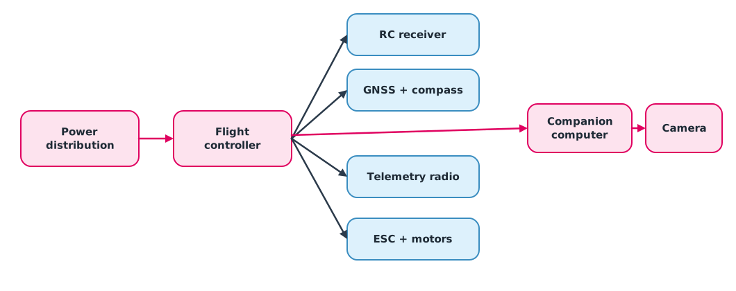
Example 1 Ordering tasks and finding the critical path
tasks = {   # task: (hours, predecessors)
    "power distribution": (3, []),
    "flight controller": (2, ["power distribution"]),
    "RC receiver": (1, ["flight controller"]),
    "GNSS + compass": (2, ["flight controller"]),
    "telemetry radio": (1, ["flight controller"]),
    "ESCs + motors": (3, ["power distribution", "flight controller"]),
    "companion computer": (3, ["power distribution", "flight controller"]),
    "camera trigger": (2, ["companion computer", "flight controller"]),
}

indeg = {t: len(p) for t, (_, p) in tasks.items()}
order, ready = [], [t for t, d in indeg.items() if d == 0]
while ready:
    t = ready.pop(0)
    order.append(t)
    for u, (_, pred) in tasks.items():
        if t in pred:
            indeg[u] -= 1
            if indeg[u] == 0:
                ready.append(u)
assert len(order) == len(tasks), "dependency cycle"

finish, prev = {}, {}
for t in order:
    d, pred = tasks[t]
    start = max((finish[p] for p in pred), default=0)
    prev[t] = max(pred, key=lambda p: finish[p]) if pred else None
    finish[t] = start + d
end = max(finish, key=finish.get)
path, t = [], end
while t:
    path.append(t)
    t = prev[t]
print("order:", " -> ".join(order))
print(f"total effort {sum(d for d, _ in tasks.values())} h, earliest finish with parallel work {finish[end]} h")
print("critical path:", " -> ".join(reversed(path)))
order: power distribution -> flight controller -> RC receiver -> GNSS + compass -> telemetry radio -> ESCs + motors -> companion computer -> camera trigger
total effort 17 h, earliest finish with parallel work 10 h
critical path: power distribution -> flight controller -> companion computer -> camera triggerOne person needs the full total effort, but with two or three people the tasks on the critical path are the ones to watch; the others can slip without delaying the whole job. The program also reports immediately if the graph contains a cycle, which means the written order contradicts itself.
Allocating ports and addresses
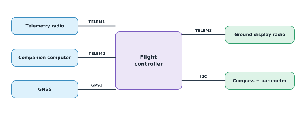
According to the ArduPilot documentation for the Pixhawk 6X, SERIAL1 is TELEM1 and SERIAL2 is TELEM2, both with RTS/CTS lines for flow control; SERIAL3 is GPS1 and SERIAL5 is TELEM3. Each port’s protocol is set with SERIALn_PROTOCOL (for example 2 = MAVLink2, 5 = GPS) and its speed with SERIALn_BAUD (for example 57 = 57,600 and 921 = 921,600 bps). The TELEM signals on this board are 3.3 V. On an I2C bus, each device needs a unique 7-bit address; for example, the MS5611 barometer uses 0x76 or 0x77 depending on its CSB pin.
Example 2 Checking port and I2C allocation
PORTS = {"SERIAL1": {"name": "TELEM1", "flow": True}, "SERIAL2": {"name": "TELEM2", "flow": True},
         "SERIAL3": {"name": "GPS1", "flow": False}, "SERIAL5": {"name": "TELEM3", "flow": True}}
PROTO = {2: "MAVLink2", 5: "GPS"}
plan = [   # device, port, SERIALn_PROTOCOL, SERIALn_BAUD, needs flow control
    ("telemetry radio", "SERIAL1", 2, 57, False),
    ("companion computer", "SERIAL3", 2, 921, True),
    ("GNSS", "SERIAL3", 5, 115, False),
    ("ground display radio", "SERIAL5", 2, 57, False),
]
i2c = {"external bus": [("GNSS module compass", 0x0E), ("add-on compass", 0x0E), ("barometer", 0x77)]}

used, issues = {}, []
for dev, port, proto, baud, need_flow in plan:
    if port in used:
        issues.append(f"{port} used by both {used[port]} and {dev}")
    used[port] = dev
    if need_flow and not PORTS[port]["flow"]:
        issues.append(f"{dev} needs flow control but {port} ({PORTS[port]['name']}) has none")
    print(f"{port:<8}{PORTS[port]['name']:<7} {dev:<21} {PROTO[proto]:<9} baud code {baud}")
for bus, devs in i2c.items():
    seen = {}
    for dev, addr in devs:
        if addr in seen:
            issues.append(f"I2C {bus}: {dev} and {seen[addr]} both at 0x{addr:02X}")
        seen[addr] = dev
print("issues:", *issues, sep="\n  ")
free = [p for p in PORTS if p not in used]
print("free ports:", free)
SERIAL1 TELEM1 telemetry radio MAVLink2 baud code 57
SERIAL3 GPS1 companion computer MAVLink2 baud code 921
SERIAL3 GPS1 GNSS GPS baud code 115
SERIAL5 TELEM3 ground display radio MAVLink2 baud code 57
issues:
companion computer needs flow control but SERIAL3 (GPS1) has none
SERIAL3 used by both companion computer and GNSS
I2C external bus: add-on compass and GNSS module compass both at 0x0E
free ports: ['SERIAL2']This plan has three problems that really do happen: the companion computer is on the GPS port, which clashes with the GNSS and has no flow control, and two compasses of the same model sit on one bus. The fix is to move the companion computer to SERIAL2, which is free and has flow control, and to choose an add-on compass whose address can be changed, or put it on another bus.
Module lab
Lab: an integration plan for the training drone
- Write a complete interface register for the training drone using the headings in this lesson
- Draw the dependency graph and use Example 1 to find the task order and critical path
- Read the flight controller’s page in the ArduPilot or PX4 documentation and allocate ports with Example 2
- Set a pass criterion for each step, for example a GNSS 3D fix with HDOP below an agreed value, before moving on
- Have another team review the register and plan before starting
Common mistakes
Watch out
- Starting assembly without an interface register
- Connecting a device that needs flow control to a port without it
- Putting I2C devices with the same address on one bus
- Installing everything and testing only once at the end
- Guessing the SERIAL number from the port label without reading the documentation for that board
Summary
- The interface register records every connection with its protocol, voltage, rate, current and parameters
- A dependency graph gives the task order, and the critical path gives the earliest finish
- Serial ports are set with
SERIALn_PROTOCOLandSERIALn_BAUDand must match flow-control needs - Devices on the same I2C bus need unique addresses
Check your understanding
- Task A takes 2 hours; task B takes 3 hours and needs A; task C takes 1 hour and needs A. What is the earliest finish?
- What does
SERIAL2_PROTOCOL = 2mean? - Which kind of port should a companion computer sending at 921,600 bps use?
- Which address does an MS5611 barometer use with its CSB pin high?
- If the topological sort cannot place every task, what does that mean?
Answers
- hours
- TELEM2 is set to MAVLink2
- A port with flow control, such as TELEM1 or TELEM2
- 0x76
- The dependency graph has a cycle, so the written order contradicts itself
Key formulas
| Earliest finish of a task |
Key references
- National Aeronautics and Space Administration. (2016). NASA systems engineering handbook (NASA/SP-2016-6105 Rev 2). link
- INCOSE. (2023). INCOSE systems engineering handbook: A guide for system life cycle processes and activities (5th ed.). Wiley. link
- ArduPilot Dev Team. Serial port configuration. ArduPilot Copter documentation. link
- ArduPilot Dev Team. Holybro Pixhawk 6X. ArduPilot Copter documentation. link
- ArduPilot Dev Team. Parameter list (Copter stable V4.6.3). ArduPilot Copter documentation. link
- Holybro. Pixhawk baseboard pinout (Pixhawk 6X). link
- TE Connectivity. (2017). MS5611-01BA03 barometric pressure sensor datasheet. link
Further reading
Study the assigned knowledge units in advance, review media and take the module quiz
Designing and integrating drone systems
Systems engineering and V&V
In class / field
Lab or field practice from worksheets with a safety checklist
Learning evidence: Checked worksheets and quiz results