Installing the FC, GNSS and sensors
UAT 302 UAS Installation and System Integration
Lesson
By the end of this module you will be able to
- Estimate magnetic interference from power wires and set the compass mounting distance
- Set the board and compass orientation to match the real installation
- Compute the effect of the GNSS antenna offset from the IMU and set the compensation
- Check flight controller vibration levels against the ArduPilot criteria
Why this matters
The flight controller knows the aircraft’s attitude and heading from its sensors. If they are mounted in the wrong orientation, in the wrong place or near interference, the drone flies wrongly even though every part is healthy. The classic symptom is a drone circling in a growing spiral in position hold (toilet-bowling) because the compass is disturbed. UAT 205 covered sensor principles and calibration; this module focuses on installation and configuration. The drone knowledge base’s unit on IMUs and magnetometers stresses bias, noise and vibration.
Compass and power wires
Current in a wire creates a magnetic field. A long straight wire carrying current produces at distance (OpenStax University Physics), with N/A² (CODATA 2022). If the go and return wires lie close together at spacing , their fields almost cancel, leaving about when is much larger than . The compass measures the Earth’s horizontal field, which in Bangkok at the start of 2026 is about 41,168 nT (41.2 µT), with an inclination of 16.3° downwards and a declination of 0.68° west, according to WMM2025 through the British Geological Survey service.
Example 1 How far should the compass be from the battery wires?
The battery wires carry 30 A in hover. The team wants the interference to stay below 5% of the Earth’s horizontal field.
import math

MU0 = 1.25663706127e-6                         # N/A² (CODATA 2022)
H_EARTH = 41_168e-9                            # T, horizontal, Bangkok 2026 (WMM2025)
I = 30.0                                       # A

def b_single(i, r):
    return MU0 * i / (2 * math.pi * r)

def b_pair(i, s, r):                           # go-and-return pair s apart, valid for r >> s
    return MU0 * i * s / (2 * math.pi * r ** 2)

print(f"single wire at 5 cm: {b_single(I, 0.05) * 1e6:.1f} uT ({b_single(I, 0.05) / H_EARTH:.1f} x Earth's horizontal field)")
for s in (0.005, 0.02):
    for r in (0.10, 0.20):
        b = b_pair(I, s, r)
        err = math.degrees(math.atan(b / H_EARTH))
        print(f"pair {s * 1000:.0f} mm apart at {r * 100:.0f} cm: {b * 1e6:5.2f} uT = {b / H_EARTH:5.1%} of H, heading error up to {err:.1f} deg")
    r_min = math.sqrt(MU0 * I * s / (2 * math.pi * 0.05 * H_EARTH))
    print(f"  distance for 5% of H with pair {s * 1000:.0f} mm apart: {r_min * 100:.0f} cm")
single wire at 5 cm: 120.0 uT (2.9 x Earth's horizontal field)
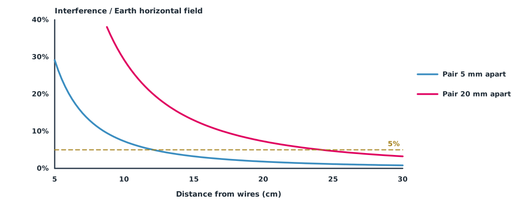
pair 5 mm apart at 10 cm: 3.00 uT = 7.3% of H, heading error up to 4.2 deg
pair 5 mm apart at 20 cm: 0.75 uT = 1.8% of H, heading error up to 1.0 deg
distance for 5% of H with pair 5 mm apart: 12 cm
pair 20 mm apart at 10 cm: 12.00 uT = 29.1% of H, heading error up to 16.3 deg
pair 20 mm apart at 20 cm: 3.00 uT = 7.3% of H, heading error up to 4.2 deg
distance for 5% of H with pair 20 mm apart: 24 cmA single wire at 5 cm produces a field almost three times the Earth’s, so the compass is useless. Laying the go and return wires together or twisting them reduces the field greatly, but if the wires are 2 cm apart the compass must be twice as far away. This is why most drones mount the GNSS and compass on a tall mast. ArduPilot’s compassmot test measures interference against real current: below 30% is acceptable, 31–60% is a grey zone, and above 60% means moving the autopilot or using an external compass.
Mounting orientation
If the flight controller must be mounted rotated from the nose direction, the software must be told. ArduPilot uses AHRS_ORIENTATION, which rotates the IMU and internal compass readings by the mounting angle; the board must then be re-levelled and rebooted. An external compass is set separately with COMPASS_ORIENT. PX4 uses SENS_BOARD_ROT. An effective check is to tilt the drone by hand and confirm that the attitude on the GCS tilts the same way on every axis, then rotate the drone and confirm that the heading changes in the right direction.
GNSS antenna position
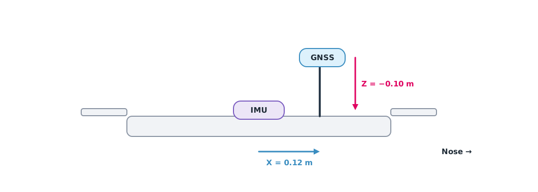
GNSS reports the position of the antenna, not of the IMU. If the antenna is offset from the IMU, the measured position moves when the drone tilts or turns even though the body has not moved. ArduPilot takes this offset in GPS1_POS_X/Y/Z in metres, with X forward, Y right and Z down, measured from the IMU (or from the CG if the IMU position is set). Newer PX4 versions use SENS_GPS0_OFFX/Y/Z instead of the older EKF2_GPS_POS_X/Y/Z. Always check parameter names against the documentation for the firmware version actually used.
Example 2 The effect of the antenna offset
The antenna is 0.12 m ahead of the IMU and 0.10 m above it (Z points down, so −0.10).
import math

X, Z = 0.12, -0.10                             # m, GPS1_POS_X and GPS1_POS_Z
for roll in (10, 25):
    shift = abs(Z) * math.sin(math.radians(roll))
    print(f"roll {roll} deg: antenna moves sideways {shift * 100:.1f} cm while the IMU stays put")
yaw_rate = math.radians(60)                    # rad/s
print(f"yaw at 60 deg/s: antenna velocity {yaw_rate * X:.3f} m/s from rotation alone")
print(f"set GPS1_POS_X = {X}, GPS1_POS_Y = 0, GPS1_POS_Z = {Z}")
roll 10 deg: antenna moves sideways 1.7 cm while the IMU stays put
roll 25 deg: antenna moves sideways 4.2 cm while the IMU stays put
yaw at 60 deg/s: antenna velocity 0.126 m/s from rotation alone
set GPS1_POS_X = 0.12, GPS1_POS_Y = 0, GPS1_POS_Z = -0.1Position moves by several centimetres when the drone tilts, and measured velocity is off by almost 0.13 m/s during a fast yaw. With ordinary GNSS errors of metres this may go unnoticed, but with centimetre-level RTK it is clear, so the offset must always be measured and entered.
Checking flight controller vibration
The ArduPilot vibration measurement page states that vibration below 30 m/s² is normally acceptable, 30–60 m/s² may cause problems, and above 60 m/s² nearly always causes position and altitude-hold problems. The clipping counter (accelerometer saturation at 16 g) should be zero or very small. The recommended mounting uses foam or gel at the corners to cut high-frequency vibration while still letting the board follow the frame’s slow motion.
Module lab
Lab: install and check the sensors
- Measure the distance from the compass to the nearest power wire and estimate interference with Example 1
- Mount the flight controller on a damping base, set
AHRS_ORIENTATIONandCOMPASS_ORIENT, and check by tilting and rotating - Measure the GNSS antenna offset and set
GPS1_POS_X/Y/Zas in Example 2 - Calibrate the compass, then run compassmot under the instructor’s supervision and record the percentage
- Hover, then read vibration and clipping from the log and compare them with the ArduPilot criteria
Common mistakes
Watch out
- Routing power wires under the compass or separating the go and return wires
- Mounting the board rotated without setting its orientation
- Not entering the GNSS antenna offset when using RTK
- Using parameter names from old articles with new firmware
- Mounting the board rigidly on a frame that vibrates strongly
Summary
- The field from power wires falls with distance and falls sharply when go and return wires are kept together; it should be a small fraction of the Earth’s horizontal field (about 41 µT in Bangkok)
- Set the mounting orientation with
AHRS_ORIENTATIONandCOMPASS_ORIENTand check by tilting for real - The GNSS antenna offset from the IMU goes in
GPS1_POS_X/Y/Zand matters greatly with RTK - Vibration below 30 m/s² and clipping near zero are the ArduPilot criteria
Check your understanding
- What field does a single wire carrying 20 A produce at 10 cm?
- An interference field of 4 µT perpendicular to a 41 µT horizontal field can shift the heading by about how many degrees?
- What should you do if compassmot gives 45%?
- The antenna is 0.1 m above the IMU. Is
GPS1_POS_Zpositive or negative? - Which ArduPilot range does a vibration level of 45 m/s² fall in?
Answers
- µT
- It is in the grey zone: move the compass away from the interference or re-route the wires, then test again
- Negative, because Z points down
- 30–60 m/s², which may cause problems; improve the damping mount or fix the source
Key formulas
| Field of a long straight wire | |
| Field of a go-and-return pair (r ≫ s) | |
| Heading error |
Key references
- Ling, S. J., Sanny, J., & Moebs, W. (2016). University physics volume 2. OpenStax. link
- National Institute of Standards and Technology. CODATA value: vacuum magnetic permeability (CODATA 2022). link
- British Geological Survey. Geomagnetism web service: World Magnetic Model WMM2025 and IGRF-14. link
- ArduPilot Dev Team. Advanced compass setup (CompassMot). ArduPilot Copter documentation. link
- ArduPilot Dev Team. Sensor position offset compensation. ArduPilot Copter documentation. link
- ArduPilot Dev Team. Parameter list (Copter stable V4.6.3). ArduPilot Copter documentation. link
- PX4 Autopilot. Parameter reference. PX4 user guide (main). link
- ArduPilot Dev Team. Measuring vibration. ArduPilot Copter documentation. link
Further reading
Study the assigned knowledge units in advance, review media and take the module quiz
PX4 and ArduPilot architecture
IMUs: gyroscopes, accelerometers and magnetometers
In class / field
Lab or field practice from worksheets with a safety checklist
Learning evidence: Checked worksheets and quiz results