Autopilot architecture
UAT 305 Autopilot and Control Technology
Lesson
By the end of this module you will be able to
- Explain the ArduPilot and PX4 software structure from sensors to motors
- Compute scheduler load from each task's rate and time
- Compute the phase lost to delay in a control loop
- Read the parameters that set the loop rates of both autopilots
Why this matters
UAT 206 taught that autopilots control in layers and which loops each flight mode uses. This course looks deeper at how the software runs in real time, because many flight problems come not from wrong tuning but from loops that run late or carry too much delay. The drone knowledge base’s unit on PX4 and ArduPilot architecture covers software structure, parameters, flight modes, failsafes and geofences. The numbers in this module refer to ArduPilot Copter 4.6.3; for other versions, check names and defaults again.
From sensors to motors
ArduPilot runs a main loop at SCHED_LOOP_RATE, whose Copter default is 400 Hz (settable range 50–400 Hz). In each cycle, fast tasks (FAST_TASK) such as the rate controller and motor output run every time, while other tasks sit in the scheduler’s task table. Each task states its rate (Hz), expected time (microseconds) and priority, for example rc_loop at 250 Hz and 130 µs, fence_check at 25 Hz and 100 µs, and ekf_check at 10 Hz and 75 µs in the 4.6.3 source code.
PX4 splits its software into modules that communicate through uORB, an asynchronous publish/subscribe messaging system between threads. The rate controller runs at the gyro publication rate set by IMU_GYRO_RATEMAX, default 400 Hz, while raw sensor data may be read and filtered at a much higher rate.
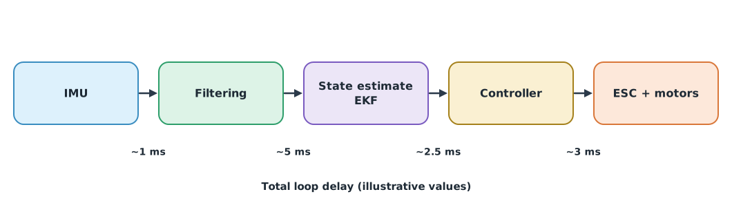
Example 1 Scheduler load
Three tasks from the Copter 4.6.3 table plus the fast-loop time measured on one board (hypothetical 700 µs). The real table has many more tasks; this is for practice.
LOOP_HZ = 400
tasks = {   # task: (rate Hz, expected time µs)
    "fast loop (rate ctrl + motors)": (400, 700),
    "rc_loop": (250, 130),
    "fence_check": (25, 100),
    "ekf_check": (10, 75),
}
period_us = 1e6 / LOOP_HZ
load = 0.0
for name, (hz, us) in tasks.items():
    share = hz * us / 1e6
    load += share
    print(f"{name:<31} {hz:>3} Hz x {us:>3} us = {share:6.1%} of CPU time")
print(f"loop period {period_us:.0f} us, total load of these tasks {load:.1%}")
for hz in (400, 800):
    print(f"if the loop ran at {hz} Hz, the fast loop alone would need {hz * 700 / 1e6:.0%}")
fast loop (rate ctrl + motors) 400 Hz x 700 us = 28.0% of CPU time
rc_loop 250 Hz x 130 us = 3.2% of CPU time
fence_check 25 Hz x 100 us = 0.2% of CPU time
ekf_check 10 Hz x 75 us = 0.1% of CPU time
loop period 2500 us, total load of these tasks 31.6%
if the loop ran at 400 Hz, the fast loop alone would need 28%
if the loop ran at 800 Hz, the fast loop alone would need 56%Just a few tasks use almost a third of the processing time, mostly the fast loop because it runs every cycle. Raising the loop rate without changing the board quickly eats the time left for other tasks, which is why the documentation warns that values above 400 Hz are experimental. If tasks overrun their expected time, the scheduler defers low-priority tasks, which shows in the performance messages in the log.
Delay eats phase
Every step from reading the IMU, filtering and computing to the motor changing thrust takes time. A pure delay does not reduce signal size but lags the phase by radians (Caltech recitation notes), or degrees at frequency . The phase lost at the loop’s crossover frequency reduces the phase margin directly, as covered in UAT 206.
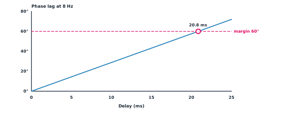
Example 2 How much delay uses up the phase margin?
The rate loop crosses over at 8 Hz and has a 60° phase margin without delay (hypothetical values).
F_C, PM0 = 8.0, 60.0                           # Hz, degrees
for tau_ms in (8, 12, 20):
    lag = 360 * F_C * tau_ms / 1000
    print(f"delay {tau_ms:>2} ms: phase lag {lag:5.1f} deg, remaining margin {PM0 - lag:5.1f} deg")
tau_zero = PM0 / (360 * F_C) * 1000
print(f"delay that removes all margin: {tau_zero:.1f} ms")
delay 8 ms: phase lag 23.0 deg, remaining margin 37.0 deg
delay 12 ms: phase lag 34.6 deg, remaining margin 25.4 deg
delay 20 ms: phase lag 57.6 deg, remaining margin 2.4 deg
delay that removes all margin: 20.8 msA delay of only 20 ms leaves so little phase margin that the loop oscillates. Filters with too low a cutoff, a slow loop or slow ESCs all add delay. Reducing delay therefore allows stronger tuning without oscillation.
Module lab
Lab: exploring timing in the autopilot
- Open
ArduCopter/Copter.cppfor the version in use, read thescheduler_taskstable, and compute the load of 10 tasks with Example 1 - Run SITL and look at the performance (PM) messages in the log, comparing real loop time with expectations
- Change
SCHED_LOOP_RATEin SITL, observe the result, then restore the default - Estimate the total loop delay from the steps in Figure 1 and compute the phase lost with Example 2
- Compare with the PX4 structure from the uORB documentation and controller diagrams
Common mistakes
Watch out
- Raising the loop rate beyond the board’s capacity without checking scheduler load
- Setting filters very low to reduce noise, forgetting the added delay
- Using defaults from another firmware version
- Treating small delays as unimportant
- Blaming the tuning when the real problem is a loop running late
Summary
- ArduPilot Copter runs a 400 Hz main loop by default; fast tasks run every cycle and others sit in a table with rates, times and priorities
- PX4 uses uORB between modules, and the rate controller runs at the
IMU_GYRO_RATEMAXrate - Scheduler load is the sum of rate times time for every task
- A delay costs degrees of phase and reduces the loop’s phase margin
Check your understanding
- A 50 Hz task takes 400 µs. What share of processing time is that?
- What is the period of a 400 Hz loop?
- How many degrees of phase lag does 10 ms of delay cause at 10 Hz?
- With a 45° margin at a 5 Hz crossover, how much delay can be tolerated before it is gone?
- Why can lowering a filter’s cutoff make the loop oscillate?
Answers
- ms
- s = 25 ms
- The filter adds delay and phase lag, reducing the phase margin
Key formulas
| Scheduler load | |
| Phase lost to delay |
Key references
- ArduPilot Dev Team. Scheduling code to run intermittently. ArduPilot developer documentation. link
- ArduPilot Dev Team. ArduPilot source code, tag Copter-4.6.3 [Computer software]. GitHub. link
- PX4 Autopilot. uORB messaging. PX4 guide (main). link
- PX4 Autopilot. Controller diagrams. PX4 user guide (main). link
- PX4 Autopilot. Parameter reference. PX4 user guide (main). link
- Christalin, B. (2015). Time delays and Nyquist plots review (CDS 110 recitation notes). California Institute of Technology. link
- Beard, R. W., & McLain, T. W. (2012). Small unmanned aircraft: Theory and practice. Princeton University Press. link
Further reading
Study the assigned knowledge units in advance, review media and take the module quiz
In class / field
Lab or field practice from worksheets with a safety checklist
Learning evidence: Checked worksheets and quiz results