Log-based tuning
UAT 305 Autopilot and Control Technology
Lesson
By the end of this module you will be able to
- Compute a notch filter's attenuation and phase at different frequencies
- Set ArduPilot's harmonic notch to track motor frequency
- Compute the phase that a low-pass filter adds to the control loop
- Use log analysis tools to check results before and after changes
Why this matters
UAT 303 used an FFT to find where vibration sits in frequency. This module uses the same data to set filters so that the control loop does not respond to motor vibration. Without filtering, the rate loop’s D term amplifies noise until the motors run hot; with too much filtering, the loop gains delay and oscillates (Module 1). The drone knowledge base’s unit on analysing filters from flight logs teaches reading spectra and filter effects offline, and its PX4 Flight Review and PlotJuggler units show log tools.
Notch and harmonic notch
A notch filter reduces a narrow band around frequency and passes the rest. The prototype from the W3C Audio EQ Cookbook is with bandwidth . ArduPilot uses a harmonic notch, placing filters at the fundamental and its harmonics, set with INS_HNTCH_ENABLE, INS_HNTCH_FREQ (default 80 Hz), INS_HNTCH_BW (40 Hz, typically half the base frequency), INS_HNTCH_ATT (40 dB depth) and INS_HNTCH_MODE, which selects the frequency source, for example 1 = throttle, 3 = ESC telemetry (which the documentation calls generally the best) and 4 = in-flight FFT. Motor frequency changes with throttle, so a fixed notch can miss when flying differently from when it was set.
Example 1 How much does an 80 Hz notch remove?
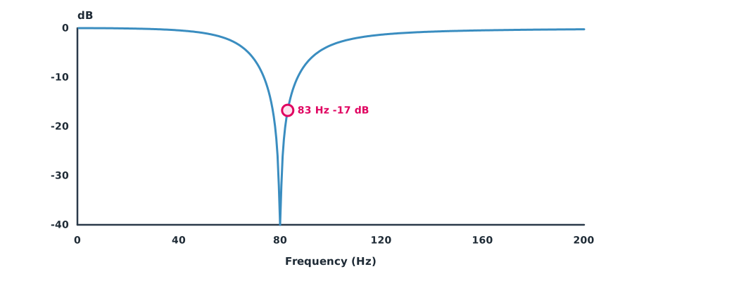
A prototype notch with = 80 Hz and = 40 Hz (unlimited depth; the real one is limited by INS_HNTCH_ATT).
import cmath
import math

F0, BW = 80.0, 40.0
Q = F0 / BW

def notch(f):
    s = 1j * f / F0
    return (s * s + 1) / (s * s + s / Q + 1)

for f in (8, 60, 80, 83, 100, 160):
    h = notch(f)
    db = 20 * math.log10(max(abs(h), 1e-5))
    print(f"{f:>3} Hz: {db:7.1f} dB, phase {math.degrees(cmath.phase(h)):6.1f} deg")
8 Hz: -0.0 dB, phase -2.9 deg
60 Hz: -2.4 dB, phase -40.6 deg
80 Hz: -100.0 dB, phase 0.0 deg
83 Hz: -16.7 dB, phase 81.6 deg
100 Hz: -3.5 dB, phase 48.0 deg
160 Hz: -0.5 dB, phase 18.4 degAt exactly 80 Hz the filter cuts deeply, but if the motors turn at 83 Hz the depth falls below 20 dB, which is why the notch should track real motor frequency. At 8 Hz, near the loop’s crossover, the notch adds only a few degrees of phase lag, so it barely affects stability, unlike lowering a low-pass cutoff.
Low-pass filters and phase
Copter’s INS_GYRO_FILTER defaults to 20 Hz and is a second-order low-pass filter in the source code. Texas Instruments’ note states that a second-order low-pass has 90° of phase lag at the cutoff and approaches 180° well above it. Even below the cutoff, the filter adds phase lag to the loop.
Example 2 Cutoff frequency and phase at an 8 Hz crossover
Computed with a second-order Butterworth low-pass ( = 0.707) for comparison.
import math

F_CROSS = 8.0
for fc in (40, 20, 10):
    r = F_CROSS / fc
    phase = -math.degrees(math.atan2(math.sqrt(2) * r, 1 - r * r))
    print(f"gyro filter {fc:>2} Hz: phase at {F_CROSS:.0f} Hz = {phase:6.1f} deg")
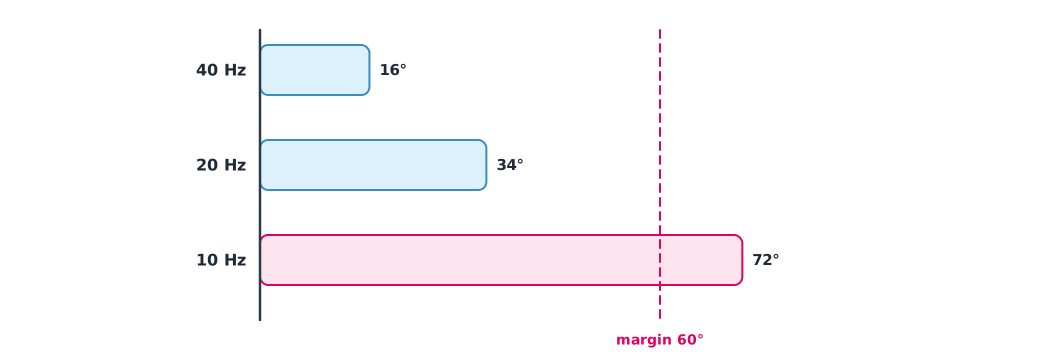
gyro filter 40 Hz: phase at 8 Hz = -16.4 deg
gyro filter 20 Hz: phase at 8 Hz = -34.0 deg
gyro filter 10 Hz: phase at 8 Hz = -72.3 degLowering the cutoff from 20 Hz to 10 Hz to reduce noise raises the phase lag at crossover from about 34° to 72°, more than the 60° phase margin of the example loop in Module 1, so the loop becomes unstable. A better approach is to use a notch to remove only the motor frequency and keep the low-pass cutoff high enough.
The log-based tuning process
ArduPilot’s tuning instructions follow an order: fix mechanical vibration first, set filters from the spectrum, then tune the rate and angle loops. After every change, fly a new log and compare with the previous one. Tools such as ArduPilot WebTools (FilterReview), PX4 Flight Review and PlotJuggler show spectra before and after filtering and compare desired with actual values.
Module lab
Lab: setting the harmonic notch from a log
- Hover with detailed IMU logging enabled and view the spectrum in FilterReview
- Find the motors’ fundamental frequency in hover and compute the attenuation with Example 1
- Set
INS_HNTCH_*for the mode the hardware supports, fly again and compare the filtered spectrum - Try low-pass cutoffs in SITL, compute the phase with Example 2 and observe the loop
- Record every change in the configuration register
Common mistakes
Watch out
- Lowering the low-pass cutoff instead of using a notch
- Setting a fixed notch when motor frequency changes with throttle
- Tuning PID before fixing vibration
- Changing several values at once so nobody knows which one worked
- Not keeping before-and-after logs, so results cannot be compared
Summary
- A notch cuts a narrow band; if the motor frequency drifts from the centre, the depth falls quickly
- ArduPilot’s harmonic notch can track motor frequency from throttle, ESC telemetry or FFT
- Low-pass filters add phase lag even below their cutoff, so lowering the cutoff risks stability
- Tune in order: fix vibration, set filters, then tune the loops, comparing logs each time
Check your understanding
- A notch with 100 Hz and 50 Hz bandwidth has what ?
- A motor at 5,400 rpm has what fundamental frequency?
- What is the phase lag of a second-order low-pass at its cutoff?
- Why does a notch affect stability less than lowering a low-pass cutoff?
- Which
INS_HNTCH_MODEdoes the documentation call generally the best?
Answers
- Hz
- 90°
- The notch acts only on a narrow band around the motor frequency, far from crossover, so it adds little phase lag at crossover
- ESC telemetry (value 3)
Key formulas
| Notch filter | |
| Phase of a second-order low-pass (Butterworth) |
Key references
- ArduPilot Dev Team. Managing gyro noise with the dynamic harmonic notch filters. ArduPilot Copter documentation. link
- Toy, R. (Ed.). (2021). Audio EQ cookbook (W3C Working Group Note). link
- Karki, J. (2023). Active low-pass filter design (SLOA049D). Texas Instruments. link
- ArduPilot Dev Team. ArduPilot source code, tag Copter-4.6.3 [Computer software]. GitHub. link
- PX4 Autopilot. Log analysis using Flight Review. PX4 guide (main). link
- ArduPilot Dev Team. Tuning process instructions. ArduPilot Copter documentation. link
Further reading
Study the assigned knowledge units in advance, review media and take the module quiz
Analysing filters from a flight log
PX4 Flight Review
PlotJuggler
In class / field
Lab or field practice from worksheets with a safety checklist
Learning evidence: Checked worksheets and quiz results