Camera and IMU calibration
UAT 307 Computer Vision and Perception Technology
Lesson
By the end of this module you will be able to
- Estimate the homography between an image and the ground plane with the DLT method
- Use a homography to measure ground distances from an oblique image
- Estimate the time offset between a camera and an IMU with cross-correlation
- Separate error sources into image parameters, mounting position and timing
Why this matters
UAT 205 calibrated the camera’s intrinsic parameters and lens distortion. The drone knowledge base’s unit on camera and IMU calibration recommends separating image parameters, mounting position and timing to find the causes of error systematically. This module adds two topics: the homography for measuring on a ground plane, and the time offset between camera and IMU, which, if uncorrected, makes visual navigation wrong every time the drone rotates.
Homography and DLT
Points on one plane (such as a landing pad) relate to their image positions through a 3×3 homography matrix with 8 degrees of freedom. Hartley and Zisserman’s Multiple View Geometry describes the DLT (direct linear transform), which uses four or more point pairs; each pair gives two linear equations, and is found with SVD. The book recommends normalising coordinates first when working with real data. OpenCV’s cv2.findHomography includes RANSAC to reject bad point pairs.
Example 1 Measuring distance on a landing pad from an oblique image
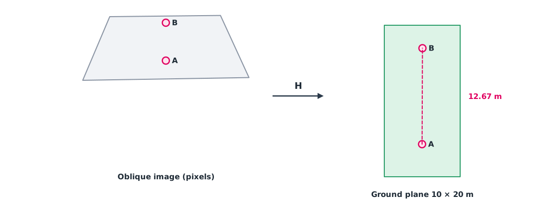
The four corners of a 10 × 20 m pad appear at these pixel positions. We want the ground distance between two points seen in the image (simulated data).
import numpy as np

img_pts = np.array([[412, 830], [1508, 812], [1320, 402], [590, 410.]])   # pixels
ground = np.array([[0, 0], [10, 0], [10, 20], [0, 20.]])                 # metres

def dlt(src, dst):
    rows = []
    for (x, y), (u, v) in zip(src, dst):
        rows.append([-x, -y, -1, 0, 0, 0, u * x, u * y, u])
        rows.append([0, 0, 0, -x, -y, -1, v * x, v * y, v])
    _, _, vt = np.linalg.svd(np.array(rows))
    h = vt[-1].reshape(3, 3)
    return h / h[2, 2]

def to_ground(H, p):
    q = H @ np.r_[p, 1.0]
    return q[:2] / q[2]

H = dlt(img_pts, ground)
a, b = to_ground(H, [960, 700]), to_ground(H, [960, 450])
print("point A on ground (m):", np.round(a, 2))
print("point B on ground (m):", np.round(b, 2))
print(f"distance A-B: {np.linalg.norm(a - b):.2f} m, while in the image they are {700 - 450} px apart")
print("check corner:", np.round(to_ground(H, img_pts[2]), 3))
point A on ground (m): [4.98 4.3 ]
point B on ground (m): [ 5.03 16.97]
distance A-B: 12.67 m, while in the image they are 250 px apart
check corner: [10. 20.]The two points are 250 pixels apart in the image but more than 12 m apart on the ground, because the top of the image is farther from the camera, so one pixel there covers more ground. A homography applies only to points on the same plane; objects with height, such as poles, project to the wrong place.
Camera–IMU time offset
Cameras and IMUs often have different clocks, and images carry exposure and transfer delays. An offset of only a few tens of milliseconds makes the fusion system believe an image was taken while the drone faced another way. Furgale et al. (2013) proposed unified temporal and spatial calibration for multi-sensor systems, as used in the Kalibr tool. The basic principle is to compare rotation signals from the two sources and find the shift that matches them best.
Example 2 Finding the time offset with cross-correlation
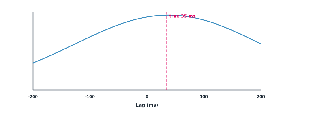
The gyro rotation rate and the rotation rate estimated from images (sampled at 200 Hz), with the image signal 35 ms late (simulated data).
import numpy as np

fs = 200
t = np.arange(0, 10, 1 / fs)
gyro = np.sin(2 * np.pi * 0.7 * t) + 0.5 * np.sin(2 * np.pi * 1.9 * t + 1)
TRUE_OFFSET = 0.035                              # s
cam = np.interp(t - TRUE_OFFSET, t, gyro) + np.random.default_rng(1).normal(0, 0.05, t.size)

lags = np.arange(-40, 41)                        # samples = ±200 ms
score = [np.dot(gyro[50:-50], np.roll(cam, -lag)[50:-50]) for lag in lags]
est = lags[int(np.argmax(score))] / fs
print(f"estimated offset {est * 1000:.0f} ms (true {TRUE_OFFSET * 1000:.0f} ms, resolution {1000 / fs:.0f} ms)")
rate = 60                                        # deg/s while yawing
print(f"at {rate} deg/s an uncorrected offset of {TRUE_OFFSET * 1000:.0f} ms means {rate * TRUE_OFFSET:.1f} deg of heading error")
estimated offset 40 ms (true 35 ms, resolution 5 ms)
at 60 deg/s an uncorrected offset of 35 ms means 2.1 deg of heading errorThe estimate is within one sample of the true value; the resolution depends on the sampling rate and can be refined by interpolating between samples. The offset looks small, but during fast yaw the computed heading is wrong by degrees, enough to degrade visual navigation.
Module lab
Lab: geometric and temporal calibration
- Place four targets at known positions on the ground, take an oblique drone image, and find the homography with Example 1
- Measure the distance between other ground points from the image and compare with a tape measure
- Compare with
cv2.findHomographyand add one wrong point to see the effect of RANSAC - Record gyro data and video while rotating the drone back and forth, and estimate the time offset with Example 2
- Study the Kalibr documentation and write a camera–IMU calibration procedure for the training drone
Common mistakes
Watch out
- Applying a homography to points not on one plane
- Using collinear point pairs, which make the equations unsolvable
- Not normalising coordinates before DLT with real data
- Not checking the camera–IMU time offset
- Calibrating once and using it forever after changing the lens or mount
Summary
- A homography maps between an image and a plane and is found with DLT from four or more point pairs
- Ground distance per pixel is not constant in an oblique image, so convert with the homography before measuring
- The camera–IMU time offset can be found by cross-correlating rotation signals
- Errors come from image parameters, mounting position or timing, and must be told apart
Check your understanding
- How many degrees of freedom does a homography have, and how many point pairs are needed at least?
- How many equations does one point pair give?
- Why is ground distance per pixel not constant in an oblique image?
- A 20 ms offset while rotating at 90 deg/s gives what heading error?
- Sampling at 100 Hz, what is the resolution of the cross-correlation time offset without interpolation?
Answers
- 8, and at least 4 pairs
- 2 equations
- One pixel far from the camera covers more ground than one pixel nearby
- 10 ms
Key formulas
| Homography | |
| DLT equations for each point pair | |
| Cross-correlation |
Key references
- Hartley, R., & Zisserman, A. (2004). Multiple view geometry in computer vision (2nd ed.). Cambridge University Press. link
- Szeliski, R. (2022). Computer vision: Algorithms and applications (2nd ed.). Springer. link
- Furgale, P., Rehder, J., & Siegwart, R. (2013). Unified temporal and spatial calibration for multi-sensor systems. In 2013 IEEE/RSJ International Conference on Intelligent Robots and Systems (pp. 1280–1286). link
- OpenCV. OpenCV documentation. link
Further reading
Study the assigned knowledge units in advance, review media and take the module quiz
In class / field
Lab or field practice from worksheets with a safety checklist
Learning evidence: Checked worksheets and quiz results