Robots and automation
UAT 308 Automation and Robotics Technology
Lesson
By the end of this module you will be able to
- Describe the parts of a mobile robot, namely sensors, actuators, controller and communication
- Use homogeneous transformation matrices to chain robot, sensor and map frames
- Compute the effect of a wheel radius error on differential-drive odometry
- Explain the map, odom and base_link frames used in ROS practice
Why this matters
UAT 314 and UAT 202 gave an overview of automation, PLCs, a two-joint arm and a two-wheeled robot. This is a practical course that builds robot systems working with drones. The case used throughout is a solar farm with an unmanned ground vehicle (UGV) that drives along panel rows, finds hotspots on panels with a thermal camera, and carries a drone to launch for high-angle surveys. The drone knowledge base’s unit on Robotics & Autonomous Systems covers robot operating systems and coordinating several systems, and its unit on industrial automation and PLCs explains actuators and control logic. The first module starts with what every robot must get right before anything else: knowing what is where, in which frame.
Parts of a mobile robot
The textbook by Siegwart et al. divides a mobile robot’s work into perception (sensors), localisation, planning and motion control (actuators). The solar-farm UGV has wheel encoders, an IMU, GNSS, a thermal camera and a LiDAR, and is driven by two DC motors. Its controller is an on-board computer running ROS 2 that talks to the control centre over a wireless network. Each sensor’s data is in its own frame, so it must be transformed into a common frame before being combined.
Homogeneous transforms and the frame tree
The position and orientation of one frame relative to another is written as a 3×3 matrix in 2D (4×4 in 3D) that combines rotation and translation. Frames are chained by multiplying matrices in order from the larger frame to the smaller one. REP 103 specifies SI units and body axes with x forward, y left and z up. The ROS tf library (Foote, 2013) stores frame relationships as a tree and computes the transforms automatically.
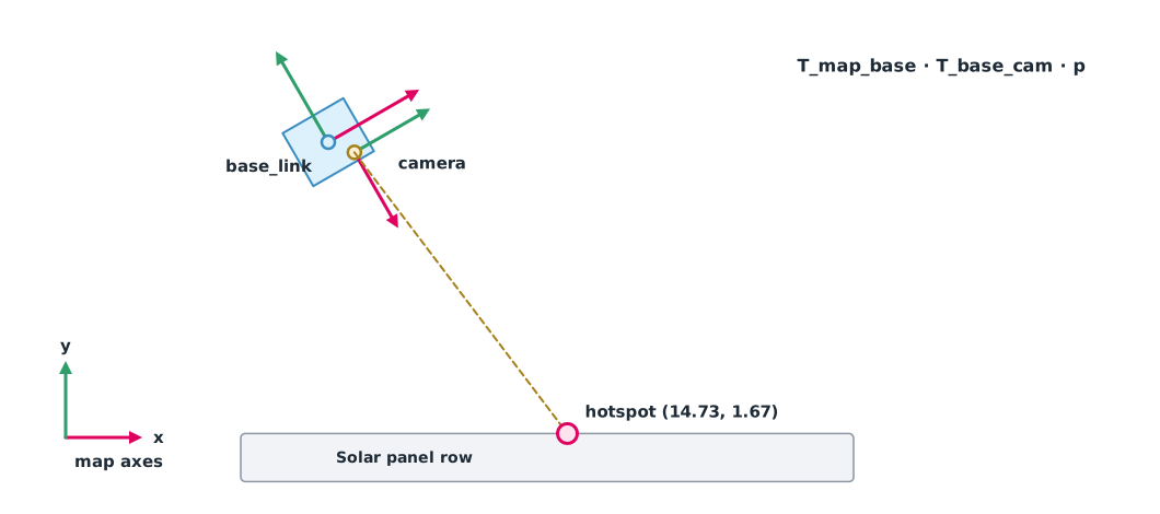
Example 1 Where on the map is the panel hotspot?
The UGV is at (12, 5) m on the map, heading 30°. The thermal camera is mounted on the right side, offset (0.20, −0.25) m from the centre and facing right (−90°). The camera sees a hotspot at (4.0, 0.5) m in the camera frame (simulated data).
import numpy as np

def se2(x, y, deg):
    t = np.radians(deg)
    return np.array([[np.cos(t), -np.sin(t), x],
                     [np.sin(t),  np.cos(t), y],
                     [0, 0, 1]])

T_map_base = se2(12.0, 5.0, 30)       # robot on the map, heading 30°
T_base_cam = se2(0.20, -0.25, -90)    # camera on the right side, facing right
p_cam = np.array([4.0, 0.5, 1])       # hotspot seen by the camera

p_map = T_map_base @ T_base_cam @ p_cam
print(f"hotspot on map: ({p_map[0]:.2f}, {p_map[1]:.2f}) m")

wrong = T_base_cam @ T_map_base @ p_cam
print(f"wrong multiplication order: ({wrong[0]:.2f}, {wrong[1]:.2f}) m")

goal = np.linalg.inv(T_map_base) @ np.array([20.0, 9.0, 1])
print(f"goal in robot frame: x = {goal[0]:.2f} m, y = {goal[1]:.2f} m")
hotspot on map: (14.73, 1.67) m
wrong multiplication order: (7.63, -15.46) m
goal in robot frame: x = 8.93 m, y = -0.54 mThe multiplication must run from map to robot to camera. With the order swapped, the result is off by many metres, enough to send a technician to the wrong panel. Finding the goal in the robot frame uses the inverse matrix; a negative y means the goal is to the robot’s right.
map, odom and base_link
REP 105 defines three main frames for mobile robots. base_link is attached to the robot. odom is a frame in which the position changes continuously without jumps but drifts with distance, which suits short-term control. map is a frame in which the position does not drift over the long term but may jump when localisation corrects it, for example when GNSS arrives or the robot matches the map. Separating frames this way keeps the wheel controller from jerking when the map position is corrected.
Odometry and systematic error
Odometry estimates position from wheel revolutions. A differential-drive robot turns when its two wheels travel different distances, . If the wheel radius used by the software differs from the real one, the error accumulates in the same direction every time. Borenstein and Feng (1996) identify two main causes, unequal wheel diameters and uncertainty in the wheel separation, and propose the UMBmark test, in which the robot drives a square path both clockwise and counter-clockwise to separate these two causes.
Example 2 A right wheel just 0.1% larger
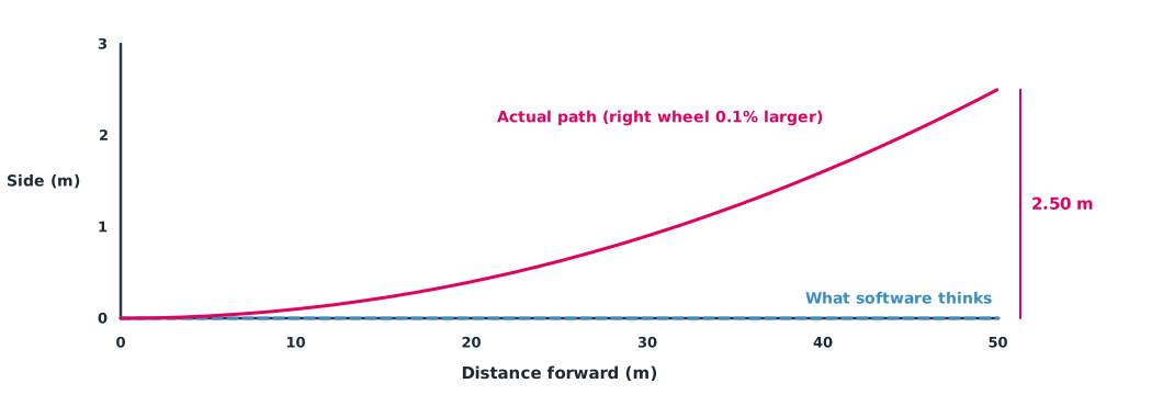
The wheel separation is 0.50 m. The software uses a radius of 0.100 m, but uneven wear has left the right wheel at 0.1001 m. The UGV is commanded to drive straight along a 50 m panel row (simulated data).
import numpy as np

b = 0.50            # wheel separation m
r_nom = 0.100       # wheel radius used by software m
r_right = 0.1001    # actual right wheel 0.1% larger
dist = 50.0         # distance software believes is straight m

rev = dist / (2 * np.pi * r_nom)          # same revolutions on both wheels
d_left = rev * 2 * np.pi * r_nom
d_right = rev * 2 * np.pi * r_right
dtheta = (d_right - d_left) / b
R = b * (d_right + d_left) / (2 * (d_right - d_left))
lateral = R * (1 - np.cos(dtheta))
print(f"actual heading change {np.degrees(dtheta):.2f} deg")
print(f"actual turn radius {R:.0f} m")
print(f"sideways offset at the end {lateral:.2f} m")
actual heading change 5.73 deg
actual turn radius 500 m
sideways offset at the end 2.50 mA difference of only 0.1 millimetre makes the robot drift about 2.5 m from the panel line within one row, enough to hit the next row. Odometry is therefore only good over short distances; wheel radius and separation must be calibrated regularly, with GNSS or map matching to correct it.
Module lab
Lab: coordinate frames and odometry calibration
- Measure the mounting positions of the LiDAR and camera on the training robot and write them as transforms relative to base_link
- Place a cone at a known position, measure it with the LiDAR, convert it to map coordinates with Example 1, and compare with a tape measure
- Drive the robot straight for 10 m five times, measure the actual sideways drift, and back-estimate the wheel radius difference with Example 2
- Run the square-path test clockwise and counter-clockwise, recording the end position relative to the start
- Summarise the corrected wheel radius and separation, with results before and after correction
Common mistakes
Watch out
- Multiplying matrices in the wrong order or inverting in the wrong direction
- Mixing degrees and radians in rotation calculations
- Measuring sensor mounting positions roughly and assuming it does not matter
- Trusting odometry over long distances with no position correction
- Feeding the map frame straight into the wheel controller, so the robot jerks when its position is corrected
Summary
- A mobile robot combines perception, localisation, planning and control
- Homogeneous transforms combine rotation and translation, and frames chain by multiplying in order
- REP 105 separates map, odom and base_link by continuity and drift
- Odometry accumulates systematic error and needs calibration and other sources to correct it
Check your understanding
- Following REP 103, which way does a robot’s y axis point?
- Which frame is continuous but drifts, and which does not drift but may jump?
- The right wheel travels 10.02 m and the left 10.00 m, with a wheel separation of 0.5 m. How many radians does the robot turn?
- If a goal in the robot frame has negative y, on which side of the robot is it?
- Why does the UMBmark test drive both clockwise and counter-clockwise?
Answers
- To the left
- odom is continuous but drifts; map does not drift but may jump
- rad
- On the right
- To separate the effect of unequal wheels from that of an uncertain wheel separation
Key formulas
| Homogeneous transform in 2D | |
| Chaining frames | |
| Heading change from wheel distances |
Key references
- Siegwart, R., Nourbakhsh, I. R., & Scaramuzza, D. (2011). Introduction to autonomous mobile robots (2nd ed.). MIT Press. link
- ROS Enhancement Proposals. REP 105: Coordinate frames for mobile platforms. link
- Foote, T., & Purvis, M. (2010). REP 103: Standard units of measure and coordinate conventions. ROS Enhancement Proposals. link
- Foote, T. (2013). tf: The transform library. In 2013 IEEE Conference on Technologies for Practical Robot Applications (TePRA) (pp. 1–6). IEEE. link
- Borenstein, J., & Feng, L. (1996). Measurement and correction of systematic odometry errors in mobile robots. IEEE Transactions on Robotics and Automation, 12(6), 869–880. link
Further reading
Study the assigned knowledge units in advance, review media and take the module quiz
Topic 3: Robotics & autonomous systems
Industrial automation and PLCs
In class / field
Lab or field practice from worksheets with a safety checklist
Learning evidence: Checked worksheets and quiz results