Indoor positioning
UAT 366 Indoor Autonomous and Multi-Unmanned Aircraft Systems
Lesson
By the end of this module you will be able to
- Combine position errors from several sources into a root-sum-square error budget
- Explain VIO drift and how known-position reference tags correct it
- Explain the external position chain into EKF2, its latency and its update rate
- Define a building coordinate frame and choose tag spacing from the acceptable error
Why this matters
Inside a warehouse there is no GNSS signal, so the drone must know its position from other sensors. UAT 363 introduced indoor positioning methods and UWB position fixes. This course asks the next question: is the position good enough to fly between racks only a few metres apart? Error comes from several sources at once. Unless the team adds them all up, it may fly closer to the racks than it realises.
The whole course uses one hypothetical case: a parts factory with a 60 × 30 m high-bay rack warehouse that uses three drones to count stock at night. All numbers are made up for practice. The Python code for every module can be downloaded from /downloads/uat-366/.
The position data chain
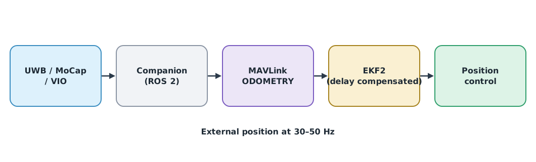
The PX4 guide to vision and motion-capture positioning says external position should be sent at 30–50 Hz; if the rate is too low, EKF2 will not fuse the data. The parameter EKF2_EV_CTRL selects whether horizontal position, vertical position, velocity or yaw is used, and EKF2_EV_DELAY sets the delay of the vision data relative to the IMU, which the guide says must be tuned experimentally. Uncompensated latency means the position being used is a past position, off by the speed multiplied by the delay.
The error budget
Independent errors from several sources combine as a root sum square (RSS). The largest source dominates, so shrinking small sources helps little.
Example 1 Position error budget in the warehouse
Assumed values (standard deviation in m); the drone flies between racks at 1.5 m/s with 40 ms of uncompensated latency.
import math

SPEED, LATENCY = 1.5, 0.040
sources = {
    "UWB position": 0.10,
    "anchor survey": 0.05,
    "uncompensated latency": SPEED * LATENCY,
    "map-to-tag offset": 0.03,
}
total = math.sqrt(sum(v ** 2 for v in sources.values()))
for name, v in sources.items():
    print(f"{name:<22} {v:.3f} m  ({v ** 2 / total ** 2:.0%} of variance)")
print(f"total (RSS) {total:.3f} m")
fixed = math.sqrt(total ** 2 - sources["uncompensated latency"] ** 2)
print(f"after compensating latency with EKF2_EV_DELAY: {fixed:.3f} m")
UWB position 0.100 m (59% of variance)
anchor survey 0.050 m (15% of variance)
uncompensated latency 0.060 m (21% of variance)
map-to-tag offset 0.030 m (5% of variance)
total (RSS) 0.130 m
after compensating latency with EKF2_EV_DELAY: 0.116 mUWB is the largest source, more than half of the variance. Compensating the latency reduces the total error by about 1.4 cm. If the aisle is 2.5 m wide and the drone is 0.8 m wide, the margin on each side is about 0.85 m, which must be compared against several standard deviations, not a single one.
VIO drift
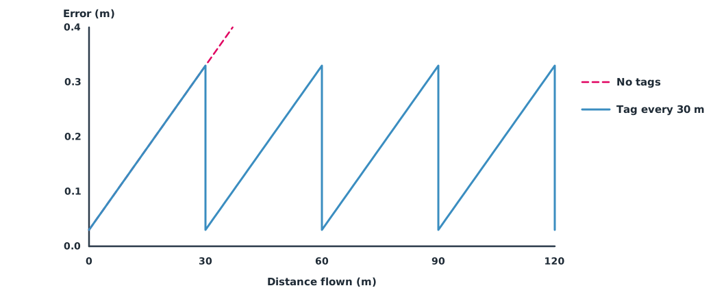
VIO (visual-inertial odometry) estimates motion from a camera and an IMU without installing anything in the building, but its error grows with distance travelled. AprilTag markers (Olson, 2011) placed at known positions reset the error whenever the camera sees one, so the error follows a sawtooth.
Example 2 Required tag spacing
Assume VIO drifts by 1% of distance travelled and a tag resets the error to 0.03 m.
DRIFT, TAG_ERR, ROUTE_M = 0.01, 0.03, 120

for spacing in (60, 30, 15):
    worst = TAG_ERR + DRIFT * spacing
    print(f"tags every {spacing:>2} m: worst error {worst:.2f} m")
print(f"no tags over {ROUTE_M} m: {TAG_ERR + DRIFT * ROUTE_M:.2f} m")
for limit in (0.20, 0.10):
    print(f"to stay below {limit:.2f} m, place tags at most every {(limit - TAG_ERR) / DRIFT:.0f} m")
tags every 60 m: worst error 0.63 m
tags every 30 m: worst error 0.33 m
tags every 15 m: worst error 0.18 m
no tags over 120 m: 1.23 m
to stay below 0.20 m, place tags at most every 17 m
to stay below 0.10 m, place tags at most every 7 mKeeping the error below 10 cm would need a tag every 7 m, which is too many. The answer is to combine sources, such as UWB with VIO, as in Module 2.
The building coordinate frame
Every source must refer to the same frame. Define the room’s origin and axis directions (for example, the south-west corner with x along the aisles), survey the UWB anchors and tags with instruments several times more accurate than the requirement, and convert to the frame PX4 uses (NED), as covered in the ENU and NED conversion in UAT 322.
Module lab
Lab: an error budget in the lab
- Define the flight room’s coordinate frame and survey the UWB anchors or motion-capture cameras and the AprilTags.
- Send external position into PX4 following the guide, check the rate and set
EKF2_EV_CTRL. - Try three values of
EKF2_EV_DELAYand compare the error while flying back and forth at a constant speed. - Measure the error of each source and use the code from Example 1 to build an error budget.
- Fly a long straight line on VIO alone, measure the drift and use the code from Example 2 to choose the tag spacing.
Common mistakes
Watch out
- Looking only at UWB accuracy without adding the other sources.
- Not compensating the latency of external data.
- Sending position more slowly than EKF2 needs.
- Mixing ENU and NED frames.
- Trusting VIO for a long time with no reference to correct its drift.
Summary
- Errors from several sources combine by RSS, and the largest source dominates the total.
- Uncompensated latency produces an error of v·Δt; set
EKF2_EV_DELAYand send data at 30–50 Hz. - VIO drifts; reference tags reset it, and tag spacing follows from the acceptable error.
- Every source must share one precisely surveyed coordinate frame.
Check your understanding
- What is the RSS of error sources of 0.06 m and 0.08 m?
- Flying at 2 m/s with 50 ms of uncompensated latency, how large is the error?
- VIO drifts 2% of distance, a tag resets the error to 0.02 m, and the limit is 0.2 m. What is the maximum tag spacing?
- At what rate does PX4 recommend sending external position?
- Why does reducing the smallest error source help so little?
Answers
- m
- m
- m
- 30–50 Hz
- RSS depends on the square of each source, so a small source contributes very little to the total.
Key formulas
| Root-sum-square error budget | |
| Error from uncompensated latency | |
| Maximum tag spacing |
Key references
- PX4 Autopilot. Using vision or motion capture systems for position estimation. PX4 guide (main). link
- Olson, E. (2011). AprilTag: A robust and flexible visual fiducial system. In 2011 IEEE International Conference on Robotics and Automation (pp. 3400–3407). IEEE. link
- IEEE. (2020). IEEE standard for low-rate wireless networks — Amendment 1: Enhanced ultra wideband (UWB) physical layers (PHYs) and associated ranging techniques (IEEE Std 802.15.4z-2020). link
- Alarifi, A., Al-Salman, A., Alsaleh, M., Alnafessah, A., Al-Hadhrami, S., Al-Ammar, M. A., & Al-Khalifa, H. S. (2016). Ultra wideband indoor positioning technologies: Analysis and recent advances. Sensors, 16(5), 707. link
- Groves, P. D. (2013). Principles of GNSS, inertial, and multisensor integrated navigation systems (2nd ed.). Artech House. link
- Siegwart, R., Nourbakhsh, I. R., & Scaramuzza, D. (2011). Introduction to autonomous mobile robots (2nd ed.). MIT Press. link
Further reading
Study the assigned knowledge units in advance, review media and take the module quiz
In class / field
Intensive lab and field practice recorded in a lab notebook
Learning evidence: Lab notebook signed by the instructor