Computer architecture
UAT 105 Digital Technology and Networks
Lesson
By the end of this module you will be able to
- Describe the parts of a von Neumann computer and the fetch–decode–execute cycle
- Explain the memory hierarchy and interrupts in systems that must respond on time
- Compare the flight controller with the companion computer on a drone
- Choose UART, I²C, SPI or CAN for a device, and calculate bus and storage capacity
Why this matters
A drone carries at least one computer that must read sensors hundreds of times a second and command the motors on time. Pick the wrong board, wire a device to the wrong bus, or use a memory card that cannot write fast enough, and video stutters or logs are lost. At worst, the control system reacts too late to keep the aircraft stable. Understanding computer architecture lets you read board specifications and design a system with enough resources.
The von Neumann computer
Almost every computer, from the microcontroller in a flight controller to a cloud server, has the same main parts:
- The central processing unit (CPU), made of a control unit that fetches and decodes instructions, an arithmetic logic unit (ALU) built from the adders and gates of module 1, and registers, tiny memories that are the fastest of all
- Memory, which holds both program instructions and data
- Input/output (I/O) devices such as sensors, motor drivers and radios
- Buses, the signal lines linking everything, split into address, data and control buses
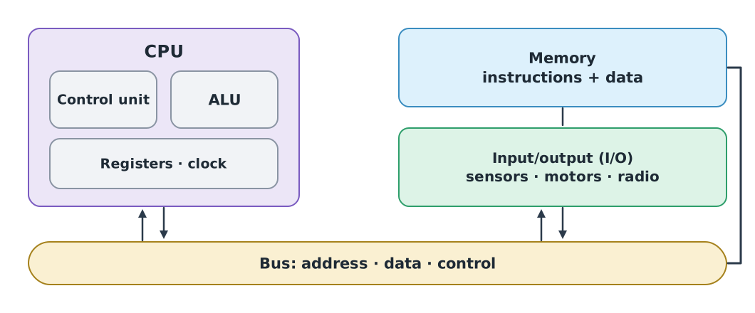
The CPU runs an endless cycle: fetch an instruction from memory, decode it, then execute it. The clock sets the pace. A 480 MHz clock ticks 480 million times a second.
The width of the address bus sets how many memory locations it can point to. A 32-bit system addresses locations; at one byte each, that is 4 GiB.
clock_hz = 480e6
print(f"clock period {1e9 / clock_hz:.3f} ns")
print(2**32, "addresses =", 2**32 / 2**30, "GiB")
clock period 2.083 ns
4294967296 addresses = 4.0 GiBThe memory hierarchy and interrupts
Fast memory is expensive and small, so memory is arranged in layers: registers inside the CPU (fastest, smallest) → cache → RAM, the main memory that is lost when power goes off → persistent storage such as flash, SD cards or SSDs, which is large but slowest. Fast programs keep the data they need in the upper layers as much as possible.
A flight controller must react immediately, for instance when the IMU has a new sample ready. Having the CPU keep asking the device (polling) wastes cycles, so devices raise an interrupt: a signal that makes the CPU pause its current work to run a short urgent task first. A real-time operating system such as NuttX, which PX4 uses on flight controllers, schedules tasks by priority so that flight control is never blocked by other work.
The two computers on a drone
Modern drones often split work between two kinds of computer.
| Flight controller | Companion computer | |
|---|---|---|
| Example | Pixhawk 6X | Raspberry Pi 5 |
| Processor | STM32H753 Arm Cortex-M7 480 MHz | Broadcom BCM2712 quad-core Arm Cortex-A76 2.4 GHz |
| Memory | 2 MB flash, 1 MB RAM | LPDDR4X 1–16 GB |
| Operating system | Real-time OS (NuttX) | Linux |
| Role | Read sensors, estimate state, drive motors | Image processing, AI, mission planning, networking |
| Strength | Guaranteed, timely response | Lots of computing power and software |
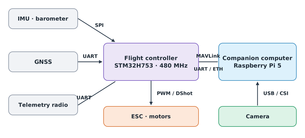
The flight controller has only 1 MB of RAM, which is enough for its specialised job. The Raspberry Pi 5 is many times faster, but Linux does not guarantee response times, so it should not drive the motors directly. The two computers talk MAVLink over UART or Ethernet.
On-board buses
| Bus | Wires | Character | Used for |
|---|---|---|---|
| UART | 2 (TX, RX) | No shared clock; both sides set the same baud rate; point to point | GNSS, telemetry radio, companion computer |
| I²C | 2 (SDA, SCL) | Several devices on one line, selected by address; moderate speed | Compass, rangefinder, small display |
| SPI | 4 or more | Shared clock, fast, a separate select line per device | IMU, barometer, memory |
| CAN | 2 (twisted pair) | Differential signalling, resists noise, message priority | DroneCAN ESCs and GNSS |
8N1 UART sends one byte as 1 start bit, 8 data bits and 1 stop bit, 10 bits in total. At 57600 baud it can carry at most 5760 bytes per second.
Example 1 How many position messages can a telemetry radio send per second?
A GLOBAL_POSITION_INT message has 28 bytes of payload plus 12 bytes of MAVLink 2 header and CRC (unsigned), at most 40 bytes per frame.
baud = 57600
bytes_per_s = baud / 10
frame_bytes = 28 + 12
print(bytes_per_s, "byte/s")
print(bytes_per_s / frame_bytes, "GLOBAL_POSITION_INT frames/s at most")
5760.0 byte/s
144.0 GLOBAL_POSITION_INT frames/s at mostThis is the theoretical ceiling of one link. In practice the link is shared with many other messages, such as HEARTBEAT, ATTITUDE and SYS_STATUS, and you need margin for periods when noise corrupts messages, so choose message rates that leave spare capacity.
Storage and write speed
A survey drone records both flight logs and video. You must check both capacity (how long it can record) and write speed (whether it keeps up with incoming data). The SD Association defines the Video Speed Class, where the number on the symbol gives the minimum write speed; V30 means 30 MB/s.
Example 2 Can a 128 GB V30 card take the video?
Suppose the camera records 4K video at 150 Mbit/s and the flight controller writes a 50 kB/s log.
log_rate_bytes = 50_000
print(log_rate_bytes * 3600 / 1e6, "MB of log per hour")

video_mbps = 150
video_mb_per_s = video_mbps / 8
print(video_mb_per_s, "MB/s needed, fits V30:", video_mb_per_s <= 30)

card_gb = 128
minutes = card_gb * 1e9 * 8 / (video_mbps * 1e6) / 60
print(f"{minutes:.1f} min of video on {card_gb} GB")
180.0 MB of log per hour
18.75 MB/s needed, fits V30: True
113.8 min of video on 128 GBThe video needs 18.75 MB/s, below the 30 MB/s minimum of V30, so the card keeps up, and 128 GB records about 114 minutes, enough for several batteries. If the camera is set to a higher bit rate such as 300 Mbit/s (37.5 MB/s), you need V60 or better.
Module lab
Lab: exploring computers and buses
- Read the Pixhawk 6X page in the PX4 user guide, list every port with its bus type (UART, I²C, CAN, internal SPI), and compare with Figure 2.
- On a Raspberry Pi or a Linux computer, run
lscpuandfree -hto see the cores, clock speed and RAM, and compare them with the flight controller. - Start SITL following the knowledge unit on preparing a computer for a drone simulator, and see how much CPU and RAM the simulation uses.
- Work out the data budget of a 57600 baud telemetry radio sending HEARTBEAT at 1 Hz, ATTITUDE at 10 Hz and GLOBAL_POSITION_INT at 4 Hz. What percentage of capacity is used? (Find each payload size in MAVLink common.xml.)
Common mistakes
Watch out
- Comparing clock speeds across architectures: different CPU families do different amounts of work per tick
- Letting a Linux computer drive the motors directly: Linux does not guarantee response times
- Wiring TX to TX: UART lines must cross, TX of one side to RX of the other, with matching baud rates
- Forgetting start and stop bits: 57600 baud UART carries 5760 bytes per second, not 7200
- Looking only at card capacity: a card that writes too slowly drops video even when it has free space
Summary
- A von Neumann computer has a CPU, memory, I/O and buses; the CPU repeats fetch, decode and execute at the pace of the clock
- Memory is layered from small and fast to large and slow, and interrupts let the system react on time
- The flight controller focuses on timing guarantees, the companion computer on computing power; they talk MAVLink
- Match the bus to the device, and check the capacity and speed of both buses and storage before flight
Check your understanding
- What is the clock period of a 200 MHz CPU in nanoseconds?
- How many memory locations can a 16-bit address bus point to?
- What is the maximum byte rate of 115200 baud 8N1 UART?
- Why does a flight controller use a real-time OS rather than Linux?
- A camera records video at 100 Mbit/s. How many minutes fit on a 64 GB card?
Answers
- ns
- locations
- byte/s
- Because flight-control tasks must be guaranteed to finish on time every cycle, and Linux does not give that guarantee
- s, about 85.3 minutes
Key formulas
| Clock period | |
| Addresses on an n-bit address bus | |
| Byte rate of 8N1 UART | |
| Recording time on a card of capacity C |
Key references
- Harris, S. L., & Harris, D. (2021). Digital design and computer architecture: RISC-V edition. Morgan Kaufmann.
- PX4 Autopilot. Holybro Pixhawk 6X. PX4 user guide. link
- Raspberry Pi Ltd. Raspberry Pi 5 product specifications. link
- SD Association. Speed class standards for video recording. link
- MAVLink Development Team. Packet serialization. MAVLink developer guide. link
- Kurose, J. F., & Ross, K. W. (2025). Computer networking: A top-down approach (9th ed.). Pearson. link
Further reading
Study the assigned knowledge units in advance, review media and take the module quiz
Digital systems and computer architecture
Preparing a computer for drone simulators
Designing and integrating drone systems
In class / field
Lab or field practice from worksheets with a safety checklist
Learning evidence: Checked worksheets and quiz results