On-board electrical systems
UAT 203 Electrical and Electronic Systems for UAS
Lesson
By the end of this module you will be able to
- Explain a drone's power distribution architecture, from battery and distribution board to ESCs and voltage converters
- Build a power budget for every device and find the current on each voltage rail
- Choose voltage converters (BECs) and a power module with enough capacity and margin
- Identify precautions for powering the flight controller according to the ArduPilot documentation
Why this matters
A survey drone has dozens of electrical devices needing different voltages: the motors take 22 V straight from the battery, the flight controller uses 5 V and some cameras 12 V. If a converter cannot supply enough current, or the supply dips momentarily as the motors accelerate, the flight controller may reset in mid-air (a brown-out), which means the drone falls. Power distribution design is therefore directly a safety matter.
The whole course uses one hypothetical case: designing the electrical system of a 6S survey quadcopter with a 3.2 kg take-off mass and a camera on a gimbal. The Python code of every module can be downloaded from /downloads/uat-203/.
Power distribution architecture
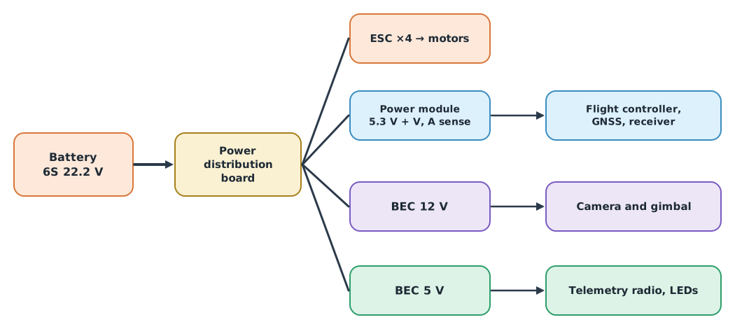
- The power distribution board (PDB) splits battery power to the ESCs and other devices, and must carry the maximum total current
- The power module gives the flight controller a stable supply and senses voltage and current for the battery failsafe. Per the ArduPilot documentation, a separate stable supply reduces the risk of brown-outs resetting the controller
- A BEC (battery eliminator circuit) is a switching converter stepping battery voltage down to 5 V or 12 V for other devices
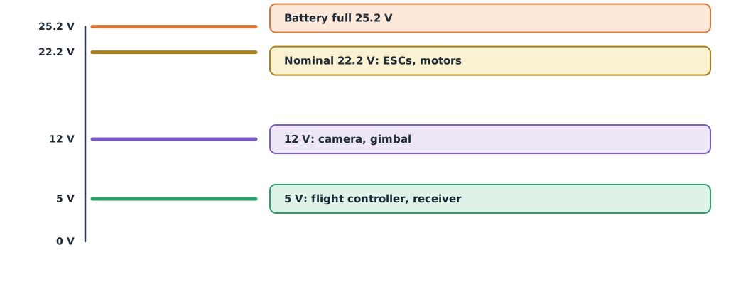
Precautions from the ArduPilot documentation
- The Pixhawk does not supply power to the servo rail; devices on the servo rail need a separate supply
- Never connect two BECs directly in parallel; for a backup supply, isolate them with diodes
- If the servo rail is powered at a higher voltage for certain servos, that rail cannot power the flight controller
Read the “Powering the Pixhawk” page for the actual board model before connecting power.
The power budget
A power budget tabulates the power of every device by voltage rail, to choose converters with enough capacity and know the system’s total draw. Converters do not give power for free: output power divided by efficiency is the power drawn from the battery.
Example 1 The survey drone’s power budget
Device powers are hypothetical values for practice; real values come from each model’s datasheet, using maximum rather than average power.
loads = {  # device: (rail voltage V, maximum power W)
    "flight controller": (5, 2.5), "GNSS + compass": (5, 1.0), "RC receiver": (5, 0.5),
    "telemetry radio": (5, 2.0), "LEDs": (5, 2.0), "camera": (12, 8.0), "gimbal": (12, 6.0),
}
eta = 0.85                       # assumed converter efficiency
v_batt = 22.2
for rail in (5, 12):
    watts = sum(p for v, p in loads.values() if v == rail)
    print(f"{rail:>2} V rail: {watts:.1f} W = {watts / rail:.2f} A out; "
          f"draws {watts / eta / v_batt:.2f} A from the battery")

avionics_w = sum(p for _, p in loads.values()) / eta
hover_w, max_motor_a = 4 * 95, 4 * 25
print(f"avionics {avionics_w:.1f} W from the battery; hover propulsion {hover_w} W")
print(f"peak battery current ≈ {max_motor_a + avionics_w / v_batt:.1f} A (all motors at maximum)")
5 V rail: 8.0 W = 1.60 A out; draws 0.42 A from the battery
12 V rail: 14.0 W = 1.17 A out; draws 0.74 A from the battery
avionics 25.9 W from the battery; hover propulsion 380 W
peak battery current ≈ 101.2 A (all motors at maximum)The 5 V rail needs about 1.6 A, so a 3 A 5 V BEC leaves almost twofold margin. The electronics use only about 26 W against hundreds of watts for propulsion, but if this small supply fails, the drone falls. The peak of about 101 A sizes the PDB, wiring and connectors in module 5.
Choosing converters
- Output current must exceed the maximum load with margin, such as 1.5–2×
- Input voltage range must accept a fully charged battery (25.2 V for 6S)
- Noise: switching converters create interference; keep them away from the compass and GNSS antenna
- Measurement: the power module’s voltage and current multipliers must be calibrated (see UAT 321)
Module lab
Lab: the training drone’s power budget
- List every electrical device on the training drone, finding voltage and maximum power from each model’s datasheet.
- Enter the data into the code in Example 1 and choose BECs with at least 1.5× margin.
- Draw the training drone’s power distribution as in Figure 1, noting connector sizes and fuses (if any).
- Using a current-limited supply, power the flight controller through the power module (no propellers fitted) and measure the voltage at the controller with a multimeter.
- Open ArduPilot’s Powering the Pixhawk page and summarise the rules that apply to the lab’s board.
Common mistakes
Watch out
- Using average instead of maximum power in the budget
- Forgetting to divide by converter efficiency
- Connecting two BECs in parallel
- Assuming the servo rail powers devices by itself
- Placing converters right next to the compass or GNSS
Summary
- A drone’s power system has a battery, PDB, ESCs, a power module and BECs at several voltages
- The power budget is split by rail, uses maximum power and divides by converter efficiency
- The electronics draw little power but matter most, and need a stable supply with margin
- Follow the power requirements of the flight controller model used
Check your understanding
- 5 V devices totalling 10 W need how much output current?
- An 80%-efficient converter delivers 10 W from a 20 V battery. What input current does it draw?
- A 5 V BEC’s maximum load is 1.6 A. With 1.5× margin, what rating is needed at least?
- What is the voltage of a fully charged 6S pack, and how does it affect converter choice?
- Why is a momentary supply dip at the flight controller dangerous?
Answers
- A
- A
- A
- V; the converter must accept this maximum input voltage
- The controller may reset in mid-air, losing control so the drone falls
Key formulas
| Electrical power | |
| Converter input current |
Key references
- ArduPilot Dev Team. Power module / battery monitor. ArduPilot Copter documentation. link
- ArduPilot Dev Team. Powering the Pixhawk. ArduPilot Copter documentation. link
- Quan, Q. (2017). Introduction to multicopter design and control. Springer Singapore. link
- Horowitz, P., & Hill, W. (2015). The art of electronics (3rd ed.). Cambridge University Press.
Further reading
Study the assigned knowledge units in advance, review media and take the module quiz
In class / field
Lab or field practice from worksheets with a safety checklist
Learning evidence: Checked worksheets and quiz results