IMUs and magnetometers
UAT 205 Sensors and Instrumentation Systems
Lesson
By the end of this module you will be able to
- Explain MEMS gyroscopes and accelerometers and the error model of bias, scale factor and noise
- Calibrate an accelerometer with the six-position method
- Read an Allan deviation plot to find angle random walk and bias instability
- Correct magnetometer hard iron and explain its effect on heading
Why this matters
The IMU (inertial measurement unit) is the heart of the flight controller. It contains gyroscopes, which measure rotation rate, and accelerometers, which measure acceleration. The controller reads the IMU hundreds to thousands of times per second to hold attitude. The magnetometer measures the Earth’s magnetic field to give heading. If these sensors are slightly off, the drone tilts, drifts or flies in the wrong direction.
MEMS and the error model
Almost all drone sensors are MEMS (micro-electro-mechanical systems): micrometre-scale mechanical structures on a silicon chip. An accelerometer has a small proof mass on springs; when it accelerates, the mass moves and a capacitance changes. A MEMS gyro has a mass that vibrates continuously; when it rotates, the Coriolis force makes it vibrate along another axis (Groves, 2013).
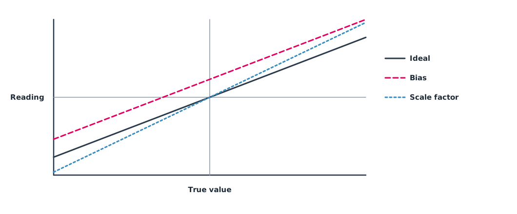
Each axis has a basic error model , where is the scale factor, the bias and the noise. Real sensors also have misaligned axes and temperature dependence. Datasheets give noise levels; TDK’s ICM-42688-P, for example, specifies gyro noise of 2.8 mdps/√Hz and accelerometer noise of 70 µg/√Hz.
Six-position accelerometer calibration
At rest, an accelerometer measures gravity with magnitude exactly . Placing each axis pointing up and then down, six positions in total, gives and readings on every axis, from which bias and scale factor follow directly. The ArduPilot guide uses these six positions (level, right side, left side, nose down, nose up and on its back), and IEEE 1293-2018 describes tumble testing of accelerometers in detail.
Example 1 Bias and scale factor from six positions
Mean at-rest readings for each position (m/s²) are hypothetical values.
import math

G = 9.80665
readings = {"x": (9.93, -9.69), "y": (9.85, -9.77), "z": (9.62, -10.02)}   # m/s² axis pointing up, pointing down

cal = {}
for axis, (up, down) in readings.items():
    bias = (up + down) / 2
    scale = (up - down) / (2 * G)
    cal[axis] = (bias, scale)
    print(f"{axis}: bias {bias:+.3f} m/s^2, scale factor {scale:.4f}")

raw = (0.12, 0.04, -10.02)            # truly level hover, z axis pointing down
fixed = [(r - cal[a][0]) / cal[a][1] for a, r in zip("xyz", raw)]
tilt = lambda v: math.degrees(math.atan2(math.hypot(v[0], v[1]), -v[2]))
print(f"apparent tilt before {tilt(raw):.2f} deg, after {tilt(fixed):.2f} deg")
x: bias +0.120 m/s^2, scale factor 1.0003
y: bias +0.040 m/s^2, scale factor 1.0003
z: bias -0.200 m/s^2, scale factor 1.0014
apparent tilt before 0.72 deg, after 0.00 degBefore calibration, the controller would believe the drone is tilted by about three quarters of a degree while it sits level, and would keep correcting until the drone drifts to one side.
Allan deviation
Recording at rest for a long time and computing the Allan deviation against averaging time separates noise types. NXP application note AN5087 and El-Sheimy et al. (2008) explain how to read this log-log plot.
- Where the curve falls with slope −1/2, the noise is white; its value on this line at s is the angle random walk (ARW).
- The flat region before the curve rises is the bias instability, the smallest amount the bias wanders. AN5087 reads the minimum directly, while the IEEE gyro standard divides the minimum by 0.664; a report must say which method it uses.
These values set the noise parameters of the EKF and help compare two sensor models before buying.
Magnetometers and hard iron
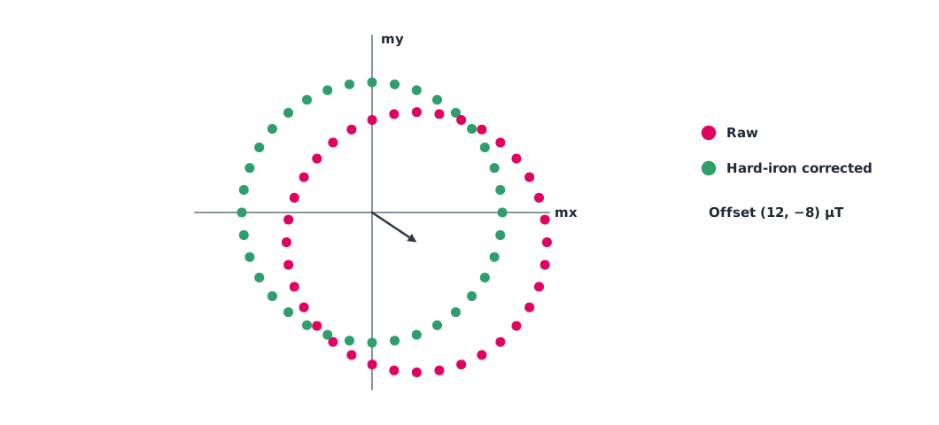
A magnetometer measures the Earth’s very weak magnetic field, so iron parts and currents on the drone disturb it easily. Hard iron is a constant field from permanent magnets or magnetised parts; it makes the data collected while rotating form a circle with a shifted centre. Soft iron from magnetically permeable materials stretches the circle into an ellipse. Compass calibration in ArduPilot or PX4 therefore asks you to rotate the drone in many directions, and ArduPilot has a CompassMot procedure to correct motor current effects.
Example 2 Correcting hard iron and comparing heading
An assumed horizontal field of 35 µT has a hard-iron offset of (12, −8) µT. The drone rotates a full turn in 10° steps. A simple 2D model measures heading from the mx axis.
import math

OFF, H = (12.0, -8.0), 35.0          # µT hard-iron offset and assumed horizontal field
samples = [(d, H * math.cos(math.radians(d)) + OFF[0], H * math.sin(math.radians(d)) + OFF[1])
           for d in range(0, 360, 10)]

def worst_error(off):
    errs = []
    for d, mx, my in samples:
        head = math.degrees(math.atan2(my - off[1], mx - off[0]))
        errs.append(abs((head - d + 180) % 360 - 180))
    return max(errs)

est = ((max(s[1] for s in samples) + min(s[1] for s in samples)) / 2,
       (max(s[2] for s in samples) + min(s[2] for s in samples)) / 2)
print(f"worst heading error without calibration: {worst_error((0, 0)):.1f} deg")
print(f"estimated offset ({est[0]:.1f}, {est[1]:.1f}) uT")
print(f"worst heading error after hard-iron correction: {worst_error(est):.1f} deg")
worst heading error without calibration: 24.3 deg
estimated offset (12.0, -8.0) uT
worst heading error after hard-iron correction: 0.0 degAn offset of about two fifths of the field magnitude puts heading off by more than 20°, enough to make the drone circle around its target (toilet bowling). Real work must also correct soft iron by fitting the ellipse back to a circle, and must recalibrate after moving equipment or changing a battery near the compass.
Compass heading is relative to magnetic north, which differs from true north by the magnetic declination, varying with place and time. ArduPilot has a built-in world magnetic model and can set it automatically. To check the value, use NOAA’s World Magnetic Model calculator (WMM2025).
Module lab
Lab: IMU and compass calibration
- Calibrate the accelerometer in six positions with Mission Planner or QGroundControl, then read the offsets and scales it produces.
- Record raw readings in the six positions yourself, compute them with the code from Example 1 and compare with the software.
- Leave the IMU still for at least an hour, record the gyro and compute the Allan deviation with a library such as AllanTools to find ARW and bias instability.
- Rotate the compass board all the way round, record mx and my, and use the code from Example 2 to find the hard iron.
- Place a steel screwdriver near the compass, observe how the circle changes and record it in the lab notebook.
Common mistakes
Watch out
- Moving the airframe during six-position calibration.
- Calibrating the compass near steel structures or cars.
- Mounting the compass near high-current wiring.
- Relying on a single datasheet value instead of measuring.
- Not recalibrating after moving equipment.
Summary
- MEMS IMUs have bias, scale factor and noise errors.
- Six-position calibration finds bias and scale factor from ±g on every axis.
- Allan deviation separates angle random walk and bias instability from at-rest data.
- Hard iron shifts the centre of the compass data circle and can make heading badly wrong; calibrate and watch for interference.
Check your understanding
- An axis reads +9.90 and −9.70 m/s². What is the bias?
- From question 1, what is the scale factor (g = 9.80665)?
- What noise type does the −1/2 slope region of an Allan deviation plot represent?
- mx ranges from −20 to 40 µT. What is the hard-iron offset on this axis?
- How do hard iron and soft iron change the shape of compass data differently?
Answers
- m/s²
- White noise, read as angle random walk.
- µT
- Hard iron shifts the circle’s centre; soft iron stretches the circle into an ellipse.
Key formulas
| Per-axis error model | |
| Six-position calibration | |
| Hard-iron centre |
Key references
- Groves, P. D. (2013). Principles of GNSS, inertial, and multisensor integrated navigation systems (2nd ed.). Artech House. link
- TDK InvenSense. ICM-42688-P high precision 6-axis MEMS motion sensor (Datasheet DS-000347). link
- Freescale Semiconductor. (2015). Allan variance: Noise analysis for gyroscopes (Application Note AN5087, Rev. 0). link
- El-Sheimy, N., Hou, H., & Niu, X. (2008). Analysis and modeling of inertial sensors using Allan variance. IEEE Transactions on Instrumentation and Measurement, 57(1), 140–149. link
- IEEE. (2019). IEEE standard specification format guide and test procedure for linear single-axis, nongyroscopic accelerometers (IEEE Std 1293-2018). link
- ArduPilot Dev Team. Accelerometer calibration. ArduPilot Copter documentation. link
- ArduPilot Dev Team. Advanced compass setup (CompassMot). ArduPilot Copter documentation. link
- NOAA National Centers for Environmental Information. (2024). The World Magnetic Model (WMM2025). link
Further reading
Study the assigned knowledge units in advance, review media and take the module quiz
In class / field
Lab or field practice from worksheets with a safety checklist
Learning evidence: Checked worksheets and quiz results