Autonomy integration
UAT 322 Artificial Intelligence and Autonomous Unmanned Aircraft Systems Integration Laboratory
Lesson
By the end of this module you will be able to
- Explain the division of work between a companion computer and the flight controller, and the uXRCE-DDS and MAVLink links between them
- Convert positions and yaw correctly between ROS ENU and PX4 NED
- Explain the requirements of Offboard and Guided modes, and simulate a watchdog for lost commands
- Estimate the latency budget from camera frame to command reaching the flight controller
Why this matters
A flight controller is excellent at holding attitude and position hundreds of times a second, but it lacks the power to run AI models or build maps. That work moves to a companion computer, such as a Jetson or Raspberry Pi board that talks to the flight controller continuously, like a co-pilot giving directions to a pilot who still holds the controls. If the two disagree about direction, or the co-pilot falls silent in mid-air, the consequences can be serious. This module practises connecting the two sides correctly and safely.
The whole course uses one hypothetical case: an autonomous survey drone with a companion computer that detects obstacles with a camera and a range sensor, tested from SITL through to the field. The Python code of every module can be downloaded from /downloads/uat-322/.
A clear division of work
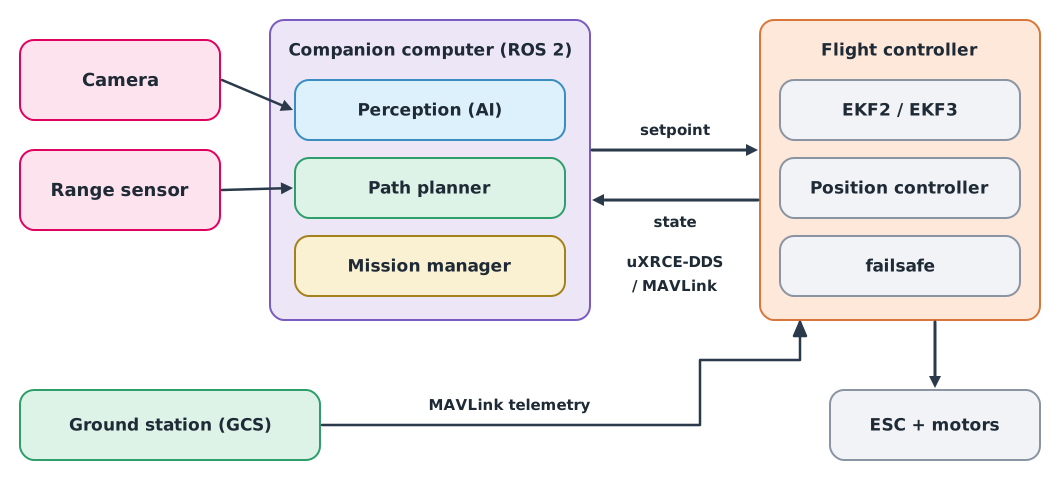
- The flight controller estimates state with its EKF, controls position and attitude, and always keeps authority over failsafes, whatever the companion computer commands
- The companion computer perceives the environment, plans paths and sends setpoints (desired position, velocity or yaw) to the flight controller
- The ground station is used to configure, monitor and abort missions
There are two main links:
| Link | Used with | Characteristics |
|---|---|---|
| uXRCE-DDS | PX4 from v1.14 with ROS 2 | PX4 uORB topics appear directly as ROS 2 topics; needs px4_msgs definitions of the matching version. In SITL the agent runs with MicroXRCEAgent udp4 -p 8888 |
| MAVLink | Both PX4 and ArduPilot | Messages such as SET_POSITION_TARGET_LOCAL_NED, sent through libraries such as MAVSDK or MAVROS |
ArduPilot also has a built-in ROS 2 interface (AP_DDS). The PX4 documentation recommends ROS 2 Jazzy on Ubuntu 24.04. With the MAVSDK library for Python, note that the mavsdk package version 4 is a new API that differs from older examples; the older examples using mavsdk_server have moved to the mavsdk-grpc package, so pin versions to match the documentation you read.
Directions must agree
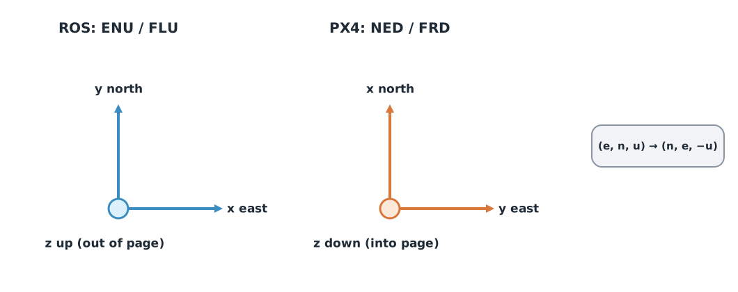
ROS uses ENU (x east, y north, z up) under REP 103, but PX4 uses NED (x north, y east, z down). Send a ROS position to PX4 without converting it, and “climb 3 metres” becomes “descend 3 metres”.
Example 1 Converting a target from ENU to NED
import math


def enu_to_ned(east, north, up):
    return north, east, -up


def yaw_enu_to_ned(yaw_enu):
    yaw = math.pi / 2 - yaw_enu
    return math.atan2(math.sin(yaw), math.cos(yaw))   # wrap into −π to π


print("target NED:", enu_to_ned(10.0, 5.0, 3.0))
for deg in (0, 90, 180):
    print(f"yaw ENU {deg:>3}° -> NED {math.degrees(yaw_enu_to_ned(math.radians(deg))):6.1f}°")
target NED: (5.0, 10.0, -3.0)
yaw ENU 0° -> NED 90.0°
yaw ENU 90° -> NED 0.0°
yaw ENU 180° -> NED -90.0°A target 10 m east, 5 m north and 3 m up becomes (north 5, east 10, down −3) in NED. ENU yaw is measured anticlockwise from east, but NED yaw clockwise from north, so facing east is 0° in ENU but 90° in NED. If a library already converts, such as PX4’s ROS 2 messages, read the documentation to see whether it has, so you do not convert twice.
When the companion computer falls silent
In PX4 Offboard mode, the companion computer must send a continuous proof-of-life signal of at least 2 Hz, and setpoints must be streaming before switching into the mode. If the signal is lost for longer than COM_OF_LOSS_T (default 1.0 s), PX4 leaves Offboard and does what COM_OBL_RC_ACT specifies (Position mode by default). In ArduPilot Guided mode, velocity commands should be re-sent every second, and the vehicle stops if none arrives for 3 seconds.
Example 2 Simulating an Offboard watchdog
The companion computer sends setpoints at 10 Hz from 0 to 3.0 s, then hangs until 4.5 s. The watchdog checks every 0.05 s.
stamps = [round(0.1 * k, 1) for k in range(31)] + [round(4.5 + 0.1 * k, 1) for k in range(11)]
LOSS_T = 1.0            # s, the default of COM_OF_LOSS_T
print("setpoints in the first second:", sum(s < 1.0 for s in stamps))

last, failsafe, i, t = None, None, 0, 0.0
while t <= 5.5:
    while i < len(stamps) and stamps[i] <= t + 1e-9:
        last = stamps[i]
        i += 1
    if last is not None and failsafe is None and t - last > LOSS_T:
        failsafe = t
    t = round(t + 0.05, 2)
print(f"failsafe at {failsafe} s (stream stopped after 3.0 s)")
setpoints in the first second: 10
failsafe at 4.05 s (stream stopped after 3.0 s)The first second holds 10 setpoints, well above the 2 Hz minimum. When the stream stops at 3.0 s, the system notices at 4.05 s; for more than a second the drone keeps following the last setpoint. Test in SITL what the drone does when the companion computer hangs before flying for real.
The latency budget
Every stage from camera to flight controller takes time; the total is the latency, during which the drone keeps moving.
stages = {"camera frame": 33, "detector": 45, "planner": 12, "DDS link": 4, "FC control": 3}   # ms
total = sum(stages.values())
speed = 5.0   # m/s
print(f"total latency {total} ms; at {speed} m/s the drone moves {speed * total / 1000:.2f} m before reacting")
total latency 97 ms; at 5.0 m/s the drone moves 0.48 m before reactingThe stage times are assumptions; measure them on your own hardware (module 4). The budget shows how much safety distance to allow, and which stage to shorten first; here the detector takes longest.
Module lab
Lab: connecting a companion computer to PX4 SITL
- Install PX4 SITL with Gazebo and ROS 2 at the versions the PX4 documentation specifies, recording every version used.
- Run
MicroXRCEAgent udp4 -p 8888and check that PX4 topics, such as vehicle position and status, appear in ROS 2. - Write a node that streams setpoints before switching into Offboard, then commands a hover at an ENU target converted to NED with the code in Example 1.
- Stop the node mid-flight, measure from the log when PX4 left Offboard, and compare with
COM_OF_LOSS_T. - Measure the real latency of the command path with timestamps on both sides, and record the results in the lab notebook.
Common mistakes
Watch out
- Sending ENU positions to PX4 unconverted, or converting twice
- Switching into Offboard before streaming setpoints, so the mode is refused or exits at once
- Letting the companion computer handle failsafes instead of the flight controller
- Using example code for a different library version, such as MAVSDK 4 with gRPC-era examples
- Not measuring real latency and using manufacturer figures instead
Summary
- The flight controller keeps stability and failsafe authority; the companion computer perceives, plans and sends setpoints
- PX4 connects to ROS 2 through uXRCE-DDS, and both PX4 and ArduPilot support MAVLink
- ROS uses ENU and PX4 uses NED; convert both position and yaw
- Offboard needs at least 2 Hz and exits when the signal is lost for longer than
COM_OF_LOSS_T - The latency budget shows how far the drone travels before reacting
Check your understanding
- What is the ENU point (east 4, north −2, up 6) in NED?
- What is an ENU yaw of 45° in NED?
- At least what rate of setpoints does PX4 Offboard mode require?
- With 120 ms total latency at 6 m/s, how far does the drone travel before reacting?
- Why should failsafes live in the flight controller rather than the companion computer?
Answers
- (north −2, east 4, down −6), or
- At least 2 Hz, and streaming must start before entering the mode
- m
- The companion computer can hang or fail, so the flight controller must decide for itself when commands are lost or abnormal
Key formulas
| ENU to NED | |
| Yaw conversion | |
| Distance travelled during latency |
Key references
- PX4 Autopilot. uXRCE-DDS (PX4-ROS 2/DDS bridge). PX4 user guide (main). link
- PX4 Autopilot. ROS 2 user guide (uXRCE-DDS bridge and frame conventions). PX4 user guide (main). link
- PX4 Autopilot. Offboard mode (multicopter). PX4 user guide (main). link
- ArduPilot Dev Team. Copter commands in Guided mode. ArduPilot developer documentation. link
- ArduPilot Dev Team. ROS 2 interfaces (AP_DDS). ArduPilot developer documentation. link
- MAVLink Development Team. MAVSDK guide. link
- Foote, T., & Purvis, M. (2010). REP 103: Standard units of measure and coordinate conventions. ROS Enhancement Proposals. link
Further reading
Study the assigned knowledge units in advance, review media and take the module quiz
PX4 and ArduPilot architecture
ROS 2 and flight-stack integration
Deep dive: from embedded systems to AI robots and ROS
Reading MAVLink telemetry from SITL
In class / field
Intensive lab and field practice recorded in a lab notebook
Learning evidence: Lab notebook signed by the instructor