Inspection work
UAT 361 Unmanned Aircraft Systems Technology for Surveying, Mapping and Inspection
Lesson
By the end of this module you will be able to
- Plan a drone structural inspection from the damage size to be seen, the stand-off distance and the lens
- Explain thermal imaging principles, including the Stefan–Boltzmann law, emissivity, reflected temperature and NETD
- Detect abnormal hot spots in a temperature grid with criteria set in advance
- State the limits of drone inspection compared with standards and other inspection methods
Why this matters
Inspection differs from mapping. Mapping asks “what is where?”; inspection asks “is this damaged, and how badly?” A crack a few millimetres wide needs images many times more detailed than a map, and hot spots on a solar panel are invisible to an ordinary camera. Drones reach high places without scaffolding, but a poor plan produces thousands of images that cannot answer the question.
Plan from the damage you must see
Start by asking how large is the smallest damage that must be seen, then decide how many pixels must span it. Lee and colleagues (2026) found that cracks only 3 pixels wide or less are measured with very high uncertainty, but they set no fixed number. The pixel count is therefore a requirement agreed between the team and the user, not a universal standard.
Then use the GSD formula from module 1, replacing height with the distance to the wall .
Example 1. Stand-off distance to see a 2 mm crack
The team requires a 2 mm crack to span at least 4 pixels. Compare a wide-angle lens with a zoom lens on the same sensor.
SENSOR_W, PX_W = 13.2, 5472          # mm, pixels
CRACK_MM, PX_ACROSS = 2.0, 4
gsd_mm = CRACK_MM / PX_ACROSS

for name, focal in (("wide 8.8 mm", 8.8), ("zoom 50 mm", 50.0)):
    distance_m = gsd_mm * focal * PX_W / SENSOR_W / 1000
    width_m = distance_m * SENSOR_W / focal
    print(f"{name}: GSD {gsd_mm} mm needs distance <= {distance_m:.1f} m, image covers {width_m:.2f} m of wall")
wide 8.8 mm: GSD 0.5 mm needs distance <= 1.8 m, image covers 2.74 m of wall
zoom 50 mm: GSD 0.5 mm needs distance <= 10.4 m, image covers 2.74 m of wallThe wide-angle lens must fly less than 2 m from the wall, which risks collision and turbulent air close to the building. The zoom lens gives the same detail at about 10 m. Both cover the same 2.74 m of wall per image, because the GSD and pixel count are the same; what differs is the safety margin. Images through a zoom lens are more sensitive to aircraft vibration, so a steady gimbal and a fast enough shutter are needed, and whatever the lens, millimetre-level inspection needs many images.
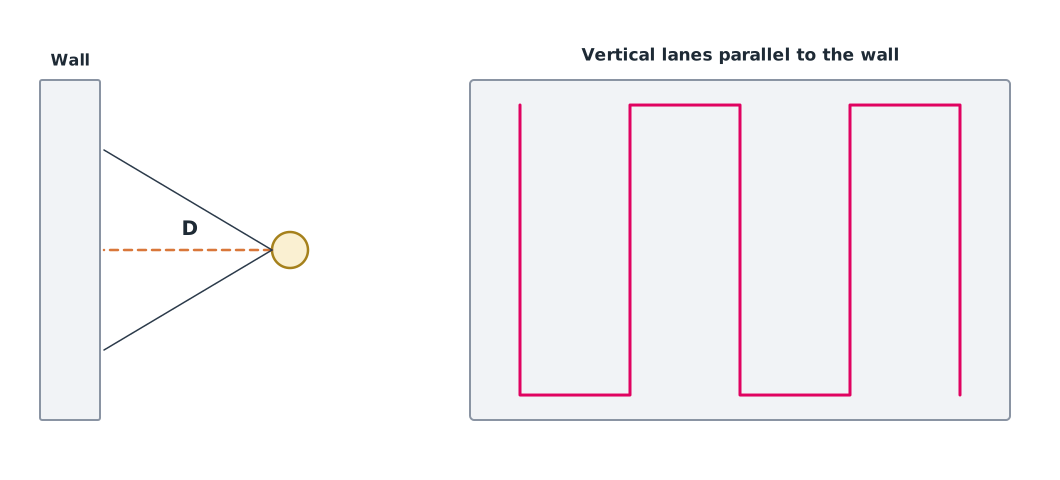
Facade inspection lanes usually run vertically or horizontally parallel to the wall at a constant distance, with enough overlap to mosaic the images or build a model, and with the camera perpendicular to the wall so crack sizes are not distorted. Every image must be locatable on the structure so the repair team can find the spot.
Thermal imaging
Every object above absolute zero emits infrared radiation. The Stefan–Boltzmann law says a perfect blackbody emits power per unit area . Real objects emit less, scaled by their emissivity (), between 0 and 1. Vollmer and Möllmann explain that for an opaque object, the part not emitted () is reflected. The camera therefore receives both the object’s own radiation and radiation from the surroundings reflected by it, represented by the reflected temperature ().
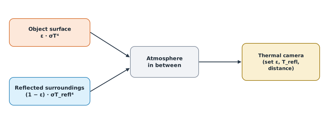
Example 2. How wrong is the reading with the wrong emissivity?
A simplified model over all wavelengths with no atmosphere (real cameras measure only their own wavelength band, so these numbers show the trend only).
SIGMA = 5.670374419e-8

def to_k(c): return c + 273.15

def received(t_obj_c, eps, t_refl_c):
    return eps * SIGMA * to_k(t_obj_c) ** 4 + (1 - eps) * SIGMA * to_k(t_refl_c) ** 4

def read_temp(w, eps_set, t_refl_c):
    return ((w - (1 - eps_set) * SIGMA * to_k(t_refl_c) ** 4) / (eps_set * SIGMA)) ** 0.25 - 273.15

w = received(60.0, 0.85, 30.0)          # true object 60 °C, true emissivity 0.85
for eps_set in (0.85, 0.95, 1.00):
    print(f"camera set eps {eps_set:.2f}: reads {read_temp(w, eps_set, 30.0):.1f} °C")
camera set eps 0.85: reads 60.0 °C
camera set eps 0.95: reads 57.2 °C
camera set eps 1.00: reads 56.0 °CSetting the emissivity higher than the true value makes the camera read about 3–4 degrees low in this example. Comparing temperature differences between panels of the same type is therefore more reliable than reading absolute temperatures. Shiny surfaces such as solar panel glass can reflect the sky or the sun into the camera, so choose viewing angles that avoid reflections.
NETD (noise equivalent temperature difference) is the smallest temperature difference the camera can resolve, in mK; lower is more sensitive. Thermal cameras have far fewer pixels than colour cameras, for example 640 × 512, so the GSD of the thermal camera must always be computed separately.
Solar panels and other structures
Outdoor thermography of solar panels is covered by the technical specification IEC TS 62446-3:2017, which sets inspection conditions and the classification of anomalies. The IEA PVPS report recommends imaging when irradiance exceeds 600 W/m², with no clouds and low wind, because the panels must be carrying real current for defects to heat up enough to be seen. (The 600 W/m² value is quoted from the IEA PVPS report and was not checked against the table in the IEC specification itself.)
Example 3. Finding hot spots in a temperature grid
The mean temperatures of an assumed array of 3 rows by 8 panels are compared with the median of all panels. The team set criteria in advance: 5 K or more above the median means re-inspect, and 10 K or more means report immediately (the team’s criteria, not the levels in the IEC specification).
from statistics import median

temps = [  # °C per panel
    [44.8, 45.1, 45.3, 44.9, 45.6, 45.0, 44.7, 45.2],
    [45.4, 45.0, 62.3, 45.1, 44.9, 45.5, 45.3, 44.8],
    [45.0, 44.6, 45.2, 45.8, 51.4, 45.1, 45.0, 45.3],
]
ref = median(t for row in temps for t in row)
print(f"median {ref:.2f} °C")
for r, row in enumerate(temps, 1):
    for c, t in enumerate(row, 1):
        dt = t - ref
        if dt >= 5:
            level = "report now" if dt >= 10 else "re-inspect"
            print(f"row {r} panel {c}: {t:.1f} °C, dT {dt:+.1f} K -> {level}")
median 45.10 °C
row 2 panel 3: 62.3 °C, dT +17.2 K -> report now
row 3 panel 5: 51.4 °C, dT +6.3 K -> re-inspectThe median is used instead of the mean because a few abnormally hot panels do not pull it upwards. Every hot spot must be confirmed with colour images (it could be bird droppings or shade) and checked again on the ground before concluding that a panel is faulty.
The limits of drone inspection must be stated plainly to the user. The US bridge inspection standards (NBIS 2022) say drones may be used to supplement inspection by qualified personnel but cannot replace tasks that need contact, such as sounding with a hammer. ASTM D4788, for detecting bridge-deck delamination with thermography, was written for vehicle-mounted scanners, so applying the method from a drone must be shown to be suitable.
Module lab
Lab: wall and solar roof inspection
- Agree with the “user” the smallest damage that must be seen and how many pixels must span it
- Apply Example 1 to the lab’s real camera, choose the stand-off distance and lens, plan safe lanes along the wall and fly them under the instructor’s supervision
- Take thermal images of solar panels in the specified light conditions, recording irradiance, air temperature, wind and the emissivity and settings
- Build a temperature grid of the panels, run Example 3 with criteria agreed before seeing the results, then confirm each hot spot with colour images and a ground check
- Write an anomaly list with the location on the structure, supporting images and the action level
Common mistakes
Watch out
- Flying too close to a wall for detail instead of changing the lens
- Reading absolute temperatures without setting emissivity and reflected temperature
- Imaging solar panels in low light, when defects are not hot enough to show
- Setting hot-spot criteria after seeing the results
- Reporting that a drone can replace contact inspection
Summary
- Start from the damage size to be seen and the agreed pixel count, then compute the stand-off distance and choose the lens
- A thermal camera receives both the object’s radiation and reflected radiation; wrong emissivity or reflected temperature settings give wrong temperatures
- Find hot spots by their difference from the median, with criteria set in advance, then confirm them by another method
- Drones supplement inspection by qualified personnel; they do not replace contact inspection
Check your understanding
- A GSD of 0.5 mm is required with a 50 mm lens and a 13.2 mm, 5472-pixel sensor. What is the maximum distance from the wall?
- How much power per unit area does a blackbody at 300 K emit?
- For an opaque object with emissivity 0.9, what fraction is reflected?
- Which thermal camera is more sensitive, one with 30 mK NETD or one with 50 mK?
- Why is the median used instead of the mean as the reference when looking for hot spots?
Answers
- mm ≈ 10.4 m
- W/m²
- 30 mK
- A few abnormally hot panels do not shift the median, but they pull the mean upwards
Key formulas
| Stand-off distance for a required GSD | |
| Stefan–Boltzmann law | |
| Total radiation received (simplified, no atmosphere) |
Key references
- Vollmer, M., & Möllmann, K.-P. (2017). Infrared thermal imaging: Fundamentals, research and applications (2nd ed.). Wiley-VCH. link
- Teledyne FLIR. Comparing sensitivity of thermal imaging cameras and modules (NETD). link
- International Electrotechnical Commission. (2017). Photovoltaic (PV) systems – Requirements for testing, documentation and maintenance – Part 3: Photovoltaic modules and plants – Outdoor infrared thermography (IEC TS 62446-3:2017). link
- Jahn, U., Herz, M., Köntges, M., et al. (2018). Review on infrared and electroluminescence imaging for PV field applications (Report IEA-PVPS T13-10:2018). IEA PVPS. link
- ASTM International. (2022). Standard test method for detecting delaminations in bridge decks using infrared thermography (ASTM D4788-03(2022)). link
- Federal Highway Administration. (2022). National bridge inspection standards (Final rule). Federal Register, 87(88), 27396. 23 CFR 650 Subpart C. link
- Lee, S. B., Lee, D. H., & Kim, J. (2026). An exploratory study on imaging resolution, operational parameters, and measurement uncertainty in UAV-based crack inspection. Sensors, 26(3), 1031. link
Further reading
Study the assigned knowledge units in advance, review media and take the module quiz
Structural inspection methods with drones
Principles of thermal imaging
In class / field
Intensive lab and field practice recorded in a lab notebook
Learning evidence: Lab notebook signed by the instructor