System architecture
UAT 493 Unmanned Aircraft Systems and Automation Technology Capstone Project I
Lesson
By the end of this module you will be able to
- Separate the functional architecture (what the system must do) from the physical architecture (what does it)
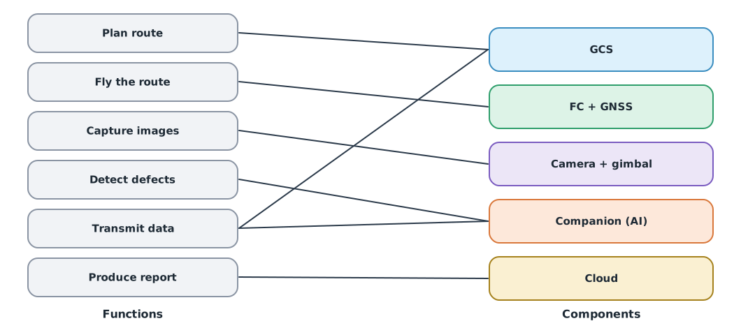
- Allocate functions to components and check that every function has an owner
- Use an N² chart to find the interfaces and the most connected components
- Build a traceability matrix from requirements to components
Why this matters
Most project problems are not inside individual parts but at the seams between them. The camera sends images and the companion computer runs the model, yet when they are connected the image format does not match, the timing does not match or there is not enough power. An architecture designed before building shows every seam on paper, where fixing it is far easier and cheaper than on the real aircraft.
From functions to components
A functional architecture says what the system must do without saying what does it. A physical architecture says which component performs each function. Keeping the two layers apart lets you change hardware without rethinking the functions.
The N² chart
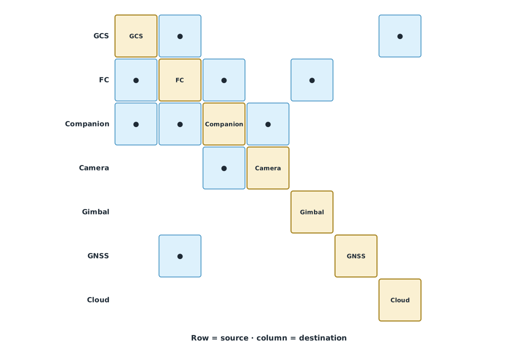
An N² chart places the components on the diagonal. The cell in row , column shows whether data or power flows from component to component . The NASA Systems Engineering Handbook presents this diagram as an interface management tool.
Example 1. Analysing the N² chart and checking the allocation
parts = ["GCS", "FC", "Companion", "Camera", "Gimbal", "GNSS", "Cloud"]
links = [("GCS", "FC"), ("FC", "GCS"), ("FC", "Companion"), ("Companion", "FC"), ("Companion", "Camera"),
         ("Camera", "Companion"), ("FC", "Gimbal"), ("GNSS", "FC"), ("Companion", "GCS"), ("GCS", "Cloud")]
n = len(parts)
print(f"{len(links)} interfaces of {n * (n - 1)} possible")
degree = {p: sum(p in link for link in links) for p in parts}
for p, d in sorted(degree.items(), key=lambda kv: -kv[1]):
    print(f"  {p:<9} {d} links")

functions = ["plan route", "fly route", "capture images", "detect defects", "transmit data", "produce report",
             "log flight data"]
allocation = {"plan route": ["GCS"], "fly route": ["FC"], "capture images": ["Camera"],
              "detect defects": ["Companion"], "transmit data": ["GCS", "Companion"], "produce report": ["Cloud"]}
missing = [f for f in functions if f not in allocation]
print("functions with no component:", missing or "none")
10 interfaces of 42 possible
FC 6 links
Companion 5 links
GCS 4 links
Camera 2 links
Gimbal 1 links
GNSS 1 links
Cloud 1 links
functions with no component: ['log flight data']FC and Companion have the most interfaces. They are where integration testing should start, and a failure there affects many parts of the system. The function “log flight data” has no component responsible for it yet; it must be allocated before design continues (for example, the FC records the log).
Traceability
Bidirectional traceability is part of requirements management in the NASA handbook. Every requirement must point to the component responsible for it, and every component must point back to the requirement that makes it necessary. A component with no requirement behind it may be unnecessary; a requirement with no component is a gap that must be fixed.
Each interface should also be detailed in an interface list (interface control): signal type, protocol, data rate, voltage, connector and the owner on each side, as covered in UAT 321 and UAT 204.
Module lab
Project deliverable: architecture document
- List the system functions from the module 2 requirements, without naming hardware yet
- Allocate the functions to the components of the concept chosen in module 3, and use Example 1 to check that no function is missed
- Build the system N² chart, identify the most connected components and plan to test those seams first
- Build an interface list giving signal type, protocol, data rate, voltage, connector and owner
- Build a traceability matrix from requirements to components and fix the gaps you find
Common mistakes
Watch out
- Starting from a shopping list with no functional architecture
- Functions with no owner, such as logging or handling off-nominal events
- Ignoring power and timing interfaces, counting only data cables
- No owner for either side of an interface
- Components with no requirement behind them because the team wanted to try something new
Summary
- The functional architecture says what to do; the physical architecture says what does it
- Every function must be allocated to a component
- An N² chart shows all interfaces and points to the most connected components, which should be tested first
- Bidirectional traceability links requirements with components and exposes gaps or excess
Check your understanding
- A system has 5 components. What is the maximum number of directed interfaces?
- In an N² chart, what does the cell in row FC, column Gimbal mean?
- What should be done with a function that no component is responsible for?
- What might a component with no requirement behind it indicate?
- Why should the seams of the most connected component be tested first?
Answers
- Data or commands flow from the FC to the gimbal
- Allocate it to a component before continuing the design
- It may be unnecessary, or a requirement may be missing; it must be checked
- A problem at that seam would affect many parts of the system
Key formulas
| Maximum number of directed interfaces among n components |
Key references
- National Aeronautics and Space Administration. (2016). NASA systems engineering handbook (NASA/SP-2016-6105 Rev 2). link
- INCOSE. (2023). INCOSE systems engineering handbook: A guide for system life cycle processes and activities (5th ed.). Wiley. link
- International Organization for Standardization. (2023). Systems and software engineering — System life cycle processes (ISO/IEC/IEEE 15288:2023). link
Further reading
Study the assigned knowledge units in advance, review media and take the module quiz
Systems engineering and V&V
Designing and integrating drone systems
In class / field
Team project work, advisor meetings and progress presentations
Learning evidence: Project milestone deliverables