System integration
UAT 494 Unmanned Aircraft Systems and Automation Technology Capstone Project II
Lesson
By the end of this module you will be able to
- Plan a bottom-up integration order and test one interface at a time
- Control the configuration of software, parameters and hardware with baselines and change requests
- Compare configurations between test runs to find why a result changed
- Track interface test results and retests
Why this matters
Parts that each work well may not work together. A camera may trigger fine when plugged into a computer directly, yet miss images when triggered through the flight controller. These problems live at the interfaces. Good integration adds one part at a time, tests every time, and records which versions were used so that causes can be traced.
Integration order
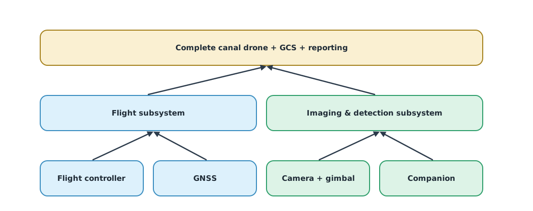
The NASA Systems Engineering Handbook and ISO/IEC/IEEE 15288 describe an integration process that assembles parts into subsystems and then into the system, level by level. This project uses bottom-up integration: test the components, combine them into the flight subsystem and the imaging-and-detection subsystem, then into the complete system with the GCS and reporting. Every interface should be recorded in an interface control document (ICD), which NASA places under configuration management.
Configuration control
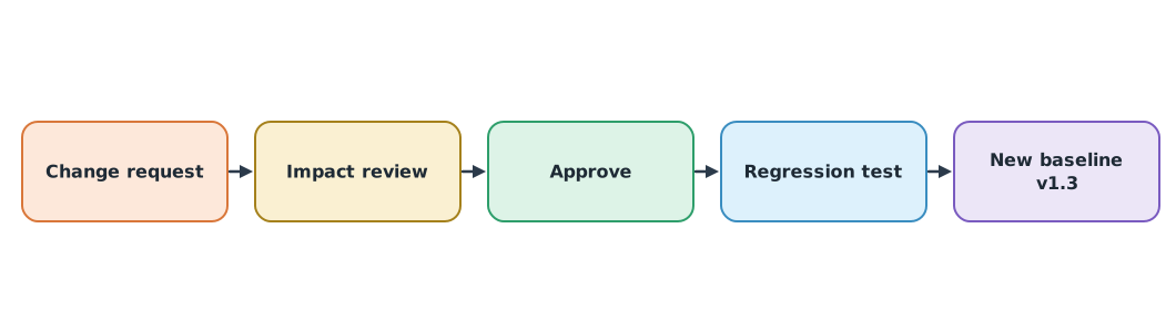
A configuration is the set of firmware and software versions, parameters, hardware and connections that makes a test result interpretable. The drone knowledge base’s exercise on version and configuration control warns that if several things change at once, nobody can tell which one changed the result. ISO 10007 gives guidance on configuration management: identify the controlled items, set a baseline, control changes through requests and reviews, and record status.
Example 1 Why more images went missing after an update
In two test runs, the first missed 1 of 210 images and the second missed 14. Compare the recorded configurations.
run_a = {"firmware": "4.5.7", "companion image": "v1.2", "CAM_TRIGG_DIST": 15.0,
         "SERIAL2_BAUD": 921, "camera fw": "1.08", "SD card": "A32"}
run_b = {"firmware": "4.5.7", "companion image": "v1.3", "CAM_TRIGG_DIST": 15.0,
         "SERIAL2_BAUD": 57, "camera fw": "1.08", "SD card": "B64"}
missed = {"run_a": 1, "run_b": 14}

changes = {k: (run_a.get(k), run_b.get(k)) for k in run_a.keys() | run_b.keys() if run_a.get(k) != run_b.get(k)}
print(f"missed images {missed['run_a']} -> {missed['run_b']}")
for k, (a, b) in sorted(changes.items()):
    print(f"changed: {k:<16} {a} -> {b}")
print(f"{len(changes)} changes at once: cannot tell which caused it; revert and change one at a time")
missed images 1 -> 14
changed: SD card A32 -> B64
changed: SERIAL2_BAUD 921 -> 57
changed: companion image v1.2 -> v1.3
3 changes at once: cannot tell which caused it; revert and change one at a timeThree simultaneous changes mean reverting and testing them one by one. Had each update gone through its own change request and retest, the team would have seen at once that lowering the serial port speed from 921,600 to 57,600 bps might delay the trigger commands.
Interface testing
Example 2 Interface test table
Results for each interface in an integration round (hypothetical). Failed interfaces must be fixed and retested, together with any interface the fix might affect.
tests = [   # (interface, first round, after fix)
    ("GCS <-> FC (MAVLink)", "pass", None),
    ("FC -> Companion (trigger)", "fail", "pass"),
    ("Companion -> Camera (USB)", "pass", None),
    ("FC -> Gimbal (PWM)", "pass", None),
    ("GNSS -> FC (UART)", "pass", None),
    ("Companion -> GCS (report)", "fail", "fail"),
    ("GCS -> Cloud (upload)", "pass", None),
]
first = sum(r == "pass" for _, r, _ in tests)
final = sum((r2 or r1) == "pass" for _, r1, r2 in tests)
print(f"first round {first}/{len(tests)} = {first / len(tests):.0%}, after fixes {final}/{len(tests)} = {final / len(tests):.0%}")
for name, r1, r2 in tests:
    if (r2 or r1) != "pass":
        print(f"open issue: {name} (still failing after fix)")
first round 5/7 = 71%, after fixes 6/7 = 86%
open issue: Companion -> GCS (report) (still failing after fix)An interface that still fails must be logged as an open issue with an owner and a target date. Never hide it to make the report look complete.
Module lab
Lab: integrate one part at a time
- Write a short ICD for every interface (signal, data format, rate, voltage, connector)
- Set baseline v1.0 of the firmware, software and parameters and keep it in version control
- Integrate in the order of Figure 1 and test every interface with a table like Example 2
- Route every change through a request, review and retest; use Example 1 to compare configurations whenever a result changes
- Log open issues with owners
Common mistakes
Watch out
- Connecting everything at once and trying to fly
- Updating several items at the same time
- Not recording the firmware and parameter versions of each test
- Not retesting affected interfaces after a fix
- Hiding open issues
Summary
- Integrate bottom-up, test every interface and record it in the ICD
- A configuration needs a baseline and changes go through requests and reviews, as in ISO 10007
- Compare configurations to find why a result changed, and change one thing at a time
- Open issues must be disclosed with owners
Check your understanding
- What is a baseline?
- Five of seven interfaces pass in the first round. What is the pass rate?
- Why should several items not be updated at once?
- What should an ICD contain?
- After fixing one interface, what must be retested?
Answers
- A reviewed and approved configuration used as the reference for later changes
- If the result changes, nobody can tell which item caused it
- Signal, data format, rate, voltage, connector, and the owner on each side
- That interface and any other interface the fix might affect
Key formulas
| Interface test pass rate |
Key references
- National Aeronautics and Space Administration. (2016). NASA systems engineering handbook (NASA/SP-2016-6105 Rev 2). link
- International Organization for Standardization. (2017). Quality management — Guidelines for configuration management (ISO 10007:2017). link
- International Organization for Standardization. (2023). Systems and software engineering — System life cycle processes (ISO/IEC/IEEE 15288:2023). link
- INCOSE. (2023). INCOSE systems engineering handbook: A guide for system life cycle processes and activities (5th ed.). Wiley. link
Further reading
Study the assigned knowledge units in advance, review media and take the module quiz
In class / field
Team project work, advisor meetings and progress presentations
Learning evidence: Project milestone deliverables