Power and wiring harness
UAT 302 UAS Installation and System Integration
Lesson
By the end of this module you will be able to
- Build a current budget for each 5 V rail and compare it with the flight controller and BEC ratings
- Check that the flight controller's supply voltage is within the manufacturer's range
- Check a wire list with a program for voltage drop, logic levels and current ratings
- Document a wiring harness so that other technicians can maintain it
Why this matters
UAT 203 covered the whole-aircraft power budget, battery wire sizing and connectors. The problems assemblers meet most often are instead on the small 5 V rails that feed the flight controller, radios, GNSS and companion computer. If a rail sags briefly, the flight controller or companion computer may reset in the air. The drone knowledge base’s unit on UAS power systems covers PDBs, BECs, wire sizes and current measurement, and its unit on PCBs and wiring harnesses covers routing and noise reduction.
Flight controller ratings
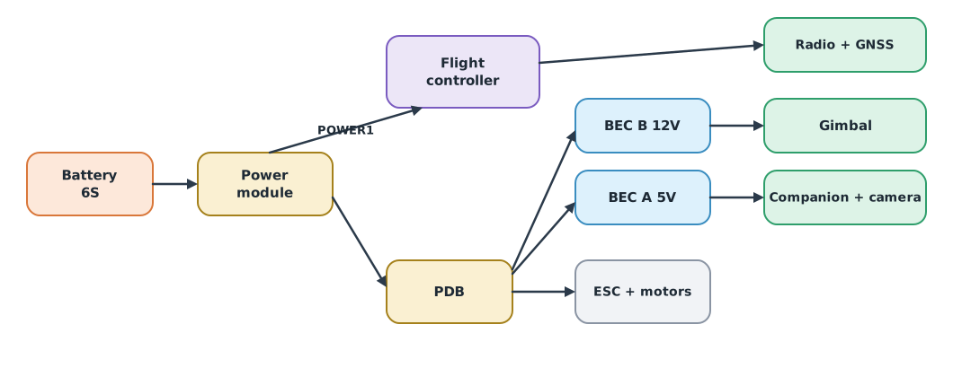
The Holybro and PX4 documentation for the Pixhawk 6X states that the POWER1/POWER2 inputs accept a normal range of 4.9–5.5 V, and that the 5 V peripheral outputs have current limiters: TELEM1 can supply 1.5 A, and all other ports together 1.5 A. The TELEM signals are 3.3 V even though their VCC pin is 5 V. ArduPilot’s page on powering the Pixhawk recommends a backup supply and warns against feeding the flight controller from the servo rail above the specified voltage. High-current devices such as the companion computer should have their own BEC.
Example 1 Current budget of the rails
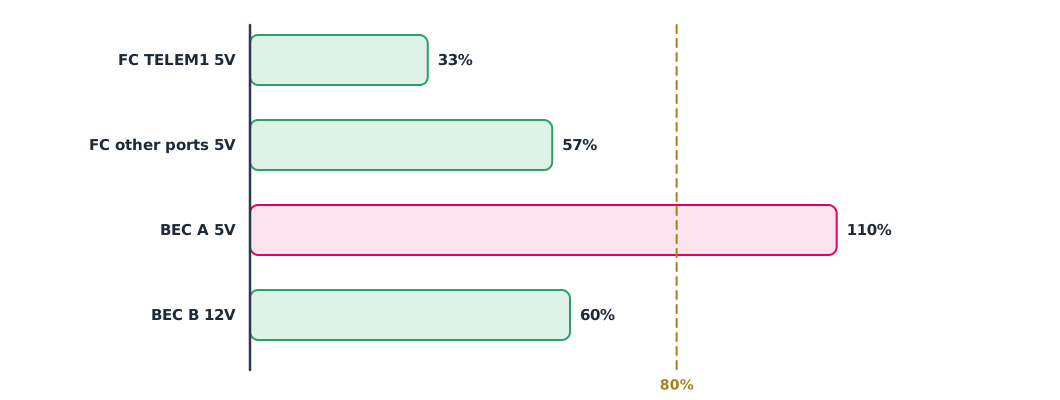
The team’s rule is that peak load must not exceed 80% of the rating. Device currents are peak values from hypothetical datasheets.
DERATE = 0.80
rails = {   # rail: (rating A, {device: peak current A})
    "FC TELEM1 5V": (1.5, {"telemetry radio": 0.5}),
    "FC other ports 5V": (1.5, {"GNSS + compass": 0.15, "RC receiver": 0.10, "ground display radio": 0.50, "LED + buzzer": 0.10}),
    "BEC A 5V": (3.0, {"companion computer": 2.5, "camera": 0.8}),
    "BEC B 12V": (2.0, {"gimbal": 1.2}),
}
for rail, (rated, loads) in rails.items():
    total = sum(loads.values())
    u = total / rated
    flag = "ok" if u <= DERATE else ("OVER RATING" if u > 1 else "above derating")
    print(f"{rail:<18} {total:.2f} / {rated:.1f} A = {u:5.1%} -> {flag}")

pm_out = 5.3                                   # V from the power module
print(f"power module {pm_out} V inside 4.9-5.5 V: {4.9 <= pm_out <= 5.5}")
FC TELEM1 5V 0.50 / 1.5 A = 33.3% -> ok
FC other ports 5V 0.85 / 1.5 A = 56.7% -> ok
BEC A 5V 3.30 / 3.0 A = 110.0% -> OVER RATING
BEC B 12V 1.20 / 2.0 A = 60.0% -> ok
power module 5.3 V inside 4.9-5.5 V: TrueThe BEC feeding the companion computer and camera has a peak load above its rating. In the lab it may look fine because the computer is not working hard, but when it processes images while the camera records, the voltage sags until it reboots in the air. Replace it with a 5 A BEC or move the camera to another rail.
The wire list
A good harness has a wire list: every wire has an ID, both end points, gauge, length, colour, signal type and voltage level. Other technicians can repair from it without guessing, and a program can check it for mistakes. Copper resistance values come from NBS Handbook 100, as in UAT 203.
Example 2 Checking the wire list
The companion computer needs at least 4.9 V at its terminals. The BEC supplies 5.1 V, and each connector has about 20 mΩ of resistance (hypothetical).
OHM_PER_KM = {20: 33.31, 22: 52.96, 24: 84.22, 26: 133.9}   # NBS Handbook 100, 20 °C
R_CONN = 0.020                                 # ohm per connector
wires = [   # id, from, to, type, AWG, round-trip length m, current A, source-side volts, load-side volts
    ("W01", "BEC A", "companion 5V", "power", 24, 0.6, 2.5, None, None),
    ("W02", "BEC A", "companion 5V", "power", 22, 0.6, 2.5, None, None),
    ("W03", "TELEM2", "companion UART", "signal", 28, 0.3, 0.0, 3.3, 3.3),
    ("W04", "TELEM3", "rangefinder UART", "signal", 28, 0.3, 0.0, 3.3, 5.0),
]
V_SRC, V_MIN = 5.1, 4.9
for wid, a, b, kind, awg, length, amps, va, vb in wires:
    if kind == "power":
        r = OHM_PER_KM[awg] * length / 1000 + 2 * R_CONN
        v = V_SRC - amps * r
        note = f"{awg} AWG: {v:.3f} V at load -> {'ok' if v >= V_MIN else 'too low'}"
    else:
        note = "logic levels match" if va == vb else f"LOGIC MISMATCH {va} V vs {vb} V, needs a level shifter"
    print(f"{wid} {a} -> {b}: {note}")
W01 BEC A -> companion 5V: 24 AWG: 4.874 V at load -> too low
W02 BEC A -> companion 5V: 22 AWG: 4.921 V at load -> ok
W03 TELEM2 -> companion UART: logic levels match
W04 TELEM3 -> rangefinder UART: LOGIC MISMATCH 3.3 V vs 5.0 V, needs a level shifterThe 24 AWG wire leaves the computer below its minimum voltage even though the wire does not get warm at all. Connector resistance matters a lot in short, high-current runs. A device with 5 V signals connected to a 3.3 V port needs a level shifter, or it may damage the flight controller’s port.
Testing before power-up
Before connecting the battery for the first time, always remove the propellers and then check in order: continuity of every wire against the wire list; no short between positive and negative on each rail; first power through a current limiter (smoke stopper) or an adjustable current-limited supply; and finally the voltage at the far end of each rail under real load.
Module lab
Lab: a harness that can be checked
- Build a current budget for every rail with Example 1 using the real device datasheets
- Write a complete wire list and label every real wire with its ID
- Check the list with Example 2 and fix wires that fail the voltage or logic-level check
- Test continuity and shorts, then power up for the first time through a current limiter with the propellers removed
- Measure the far-end voltage while the companion computer runs at full load, and record the result
Common mistakes
Watch out
- Looking only at average current, not peak current
- Connecting 5 V logic devices to 3.3 V ports without a level shifter
- Forgetting connector resistance in short high-current runs
- Powering up for the first time with propellers fitted
- Having no wire list, so nobody else can repair the harness
Summary
- Each rail needs a peak-current budget within its derated rating; the Pixhawk 6X limits TELEM1 to 1.5 A and all other ports together to 1.5 A
- The flight controller’s supply voltage must be within the manufacturer’s range
- A program can check a wire list for voltage drop, logic levels and ratings
- Test continuity and shorts, then power up the first time through a current limiter
Check your understanding
- A 3 A rail has a 2.1 A peak load. What is the utilisation, and does it pass the 80% rule?
- What is the voltage drop in a 1 m round-trip run of 22 AWG wire at 2 A (excluding connectors)?
- Why should a companion computer not be fed from a Pixhawk 6X TELEM port?
- What voltage level are the Pixhawk 6X TELEM signals?
- Why power up the first time through a current limiter?
Answers
- , which passes
- V
- Its peak current is high, above what the port can supply, and it could drag down the flight controller’s rail
- 3.3 V
- If there is a wiring mistake or short, the current is limited before parts are damaged or a fire starts
Key formulas
| Rating utilisation | |
| Voltage at the load |
Key references
- PX4 Autopilot. Holybro Pixhawk 6X. PX4 user guide. link
- Holybro. Pixhawk 6X technical specification. link
- Holybro. Pixhawk baseboard pinout (Pixhawk 6X). link
- ArduPilot Dev Team. Powering the Pixhawk. ArduPilot Copter documentation. link
- ArduPilot Dev Team. Power module / battery monitor. ArduPilot Copter documentation. link
- National Bureau of Standards. (1966). Copper wire tables (Handbook 100). link
Further reading
Study the assigned knowledge units in advance, review media and take the module quiz
In class / field
Lab or field practice from worksheets with a safety checklist
Learning evidence: Checked worksheets and quiz results