Payload installation and CG
UAT 302 UAS Installation and System Integration
Lesson
By the end of this module you will be able to
- Compute the thrust each motor must provide when the CG moves away from the thrust centre
- Set an acceptable CG envelope from the thrust margin
- Design payload vibration isolation with dampers using transmissibility
- Mount payloads so that they can be inspected and are safe
Why this matters
UAT 321 taught how to compute total mass and CG position. This module answers the installer’s next questions: how far can the CG move while flight stays safe, and how should the camera be mounted so the image does not shake? The survey drone in this case switches between a mapping camera and a thermal camera depending on the mission, and each switch changes the CG and the vibration behaviour. The drone knowledge base’s unit on payload, CG and energy recommends calculating with checkable examples and confirming with thrust experiments. All numbers are hypothetical.
A moved CG loads the motors unequally
On an X quadcopter with the CG at the centre, all four motors carry equal weight. If the CG moves forward by , the front motors must work harder to balance the moment about the CG (Quan, 2017). With the front and rear motors a fore-aft distance from the centre, each front motor’s thrust is . The harder-working motor has less thrust left for attitude control, which may not be enough in a gust or a hard stop.
Example 1 How far can the CG move before exceeding the limit?
The drone weighs 3.2 kg, the motors are 0.35 m from the centre along the diagonal, and each motor gives a maximum of 1.8 kgf. The team requires that in hover no motor uses more than 50% of its maximum thrust, leaving margin for control.
import math

G = 9.81
W = 3.2 * G                                   # N
A = 0.35 * math.cos(math.radians(45))          # m, fore-aft distance of motors from the centre
T_MAX = 1.8 * G                                # N per motor
LIMIT = 0.50

for d_cm in (0, 2, 4, 6):
    d = d_cm / 100
    tf, tr = W * (A + d) / (4 * A), W * (A - d) / (4 * A)
    share = tf / T_MAX
    print(f"CG +{d_cm} cm: front {tf:.2f} N, rear {tr:.2f} N, front motor at {share:.1%} of max -> {'ok' if share <= LIMIT else 'over limit'}")
d_max = A * (4 * LIMIT * T_MAX / W - 1)
print(f"largest CG offset within the limit: {d_max * 100:.1f} cm")
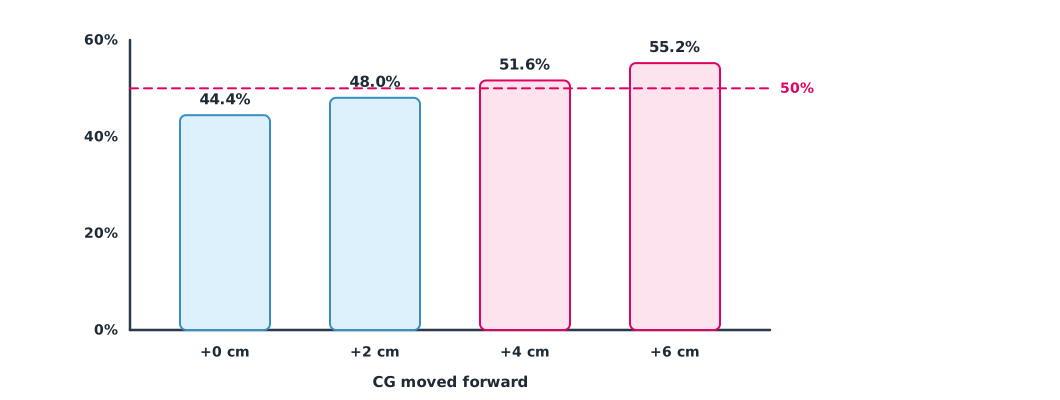
CG +0 cm: front 7.85 N, rear 7.85 N, front motor at 44.4% of max -> ok
CG +2 cm: front 8.48 N, rear 7.21 N, front motor at 48.0% of max -> ok
CG +4 cm: front 9.12 N, rear 6.58 N, front motor at 51.6% of max -> over limit
CG +6 cm: front 9.75 N, rear 5.95 N, front motor at 55.2% of max -> over limit
largest CG offset within the limit: 3.1 cmThe CG envelope of this drone is therefore about 3 cm from the thrust centre. A thermal camera mounted far forward can easily push the CG outside it. The team must move the battery backwards to balance, find the real CG by weighing, and check each motor’s output in the log after a test flight.
Isolating payload vibration
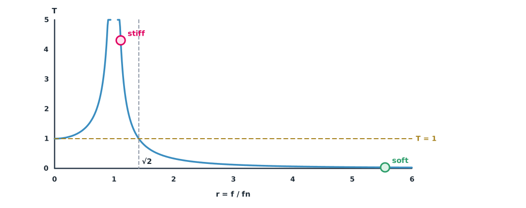
Motors and propellers vibrate at the motor rotation frequency and at the blade-pass frequency (rotation frequency times the number of blades). A camera fixed rigidly to the frame shakes with it, blurring images and overworking the gimbal. The ArduPilot and PX4 documentation recommend fixing the sources first, such as balancing propellers and stiffening the frame, and then using an isolation mount. Isolation places the payload on rubber dampers, giving the system a natural frequency under single-degree-of-freedom vibration theory (Gavin, 2026; Delli Carri). The undamped transmissibility is with . Vibration is reduced when , and if is near 1 the vibration is amplified instead.
Example 2 Choosing damper stiffness
The gimbal and camera weigh 0.9 kg on four dampers. The motors turn at 5,000 rpm with 2-blade propellers. Compare soft and stiff dampers.
import math

M = 0.9                                        # kg
RPM, BLADES = 5000, 2
f_motor = RPM / 60
f_blade = f_motor * BLADES
print(f"excitation: motor {f_motor:.1f} Hz, blade pass {f_blade:.1f} Hz")

for name, k_each in (("soft", 2_000), ("stiff", 50_000)):   # N/m per damper
    fn = math.sqrt(4 * k_each / M) / (2 * math.pi)
    parts = []
    for f in (f_motor, f_blade):
        r = f / fn
        t = 1 / abs(1 - r * r)
        parts.append(f"{f:.0f} Hz: r {r:.2f}, T {t:.3f}")
    print(f"{name:<5} fn {fn:.1f} Hz | " + " | ".join(parts))
excitation: motor 83.3 Hz, blade pass 166.7 Hz
soft fn 15.0 Hz | 83 Hz: r 5.55, T 0.034 | 167 Hz: r 11.11, T 0.008
stiff fn 75.0 Hz | 83 Hz: r 1.11, T 4.279 | 167 Hz: r 2.22, T 0.254Soft dampers cut vibration at the motor frequency to under 4%. Stiff dampers have a natural frequency close to the motor frequency, so they amplify vibration several times, which is worse than a rigid mount. But dampers that are too soft let the camera swing with the aircraft’s slow motions and may sag until the camera hits the frame, so always fit travel stops and a safety lanyard.
Mounting payloads so they can be inspected
- Use mounts designed to take loads in the flight directions, and lock screws with threadlocker or lock washers
- Route payload signal wires away from power wires, with enough slack for the gimbal to reach its full travel on every axis
- Put witness marks on critical screws so that loosening can be seen in the pre-flight check
- Record the mass, position and damper type of each payload variant in the configuration register (Module 5)
Module lab
Lab: changing payloads safely
- Find the real CG of the training drone with two payloads by hanging it or weighing on two scales
- Compute the front motor load with Example 1 and move the battery until the CG is inside the envelope
- Hover, then read each motor’s output from the log and compare it with the calculation
- Measure payload vibration with two types of damper and compare with Example 2
- Write a one-page payload change procedure for the field team
Common mistakes
Watch out
- Assuming that a drone which hovers has a correct CG
- Using stiff or soft dampers without computing the natural frequency
- No safety lanyard on a damper-mounted payload
- Routing payload cables so tight that the gimbal cannot reach full travel
- Changing payloads without recording the configuration
Summary
- A CG offset loads the motors on that side with ; the thrust margin sets the CG envelope
- Dampers isolate vibration when the excitation frequency is more than times the natural frequency
- If the natural frequency is near the motor frequency, vibration is amplified
- Mount payloads so they can be inspected, with a safety lanyard, and record them in the configuration
Check your understanding
- 30 N, 0.25 m and a CG offset of 0.05 m. What thrust does each front motor carry?
- Mass 1 kg and total stiffness 4,000 N/m. What is the natural frequency?
- With , what is the transmissibility?
- A motor at 6,000 rpm with a 3-blade propeller. What is the blade-pass frequency?
- Why can dampers that are too stiff be worse than a rigid mount?
Answers
- N
- Hz
- Hz
- The natural frequency may be near the motor frequency, causing resonance that amplifies vibration
Key formulas
| Front and rear motor thrust with CG offset d | |
| Natural frequency | |
| Transmissibility (undamped) |
Key references
- Gavin, H. P. (2026). Dynamics of simple oscillators (CEE 541 course notes). Duke University. link
- Delli Carri, A. Base excitation & isolation: Explorable explanations. Coventry University. link
- ArduPilot Dev Team. Vibration damping. ArduPilot Copter documentation. link
- PX4 Autopilot. Vibration isolation. PX4 user guide (main). link
- Quan, Q. (2017). Introduction to multicopter design and control. Springer Singapore. link
- Fahlstrom, P. G., Gleason, T. J., & Sadraey, M. H. (2022). Introduction to UAV systems (5th ed.). Wiley. link
Further reading
Study the assigned knowledge units in advance, review media and take the module quiz
Payload mass, centre of gravity and energy
Payloads and survey data quality
In class / field
Lab or field practice from worksheets with a safety checklist
Learning evidence: Checked worksheets and quiz results