Autonomous missions from SITL to field
UAT 322 Artificial Intelligence and Autonomous Unmanned Aircraft Systems Integration Laboratory
Lesson
By the end of this module you will be able to
- Plan staged testing from SITL and HITL through tethered or netted flight to the field, with pass criteria at each stage
- Report success rates with confidence intervals and calculate how many test runs are needed
- Explain and simulate run-time assurance that switches to a safe controller near a boundary
- Identify the safety and legal requirements before flying an autonomous mission for real
Why this matters
An autonomous mission that works perfectly in simulation can fail on its first real flight because of wind, sunlight, vibrating sensors or a dropped link. Testing must therefore be a staircase, adding realism one step at a time and limiting the damage when something fails, with pass criteria set at every step before seeing results. This module brings the whole course together as one mission, from SITL to the field.
The test ladder
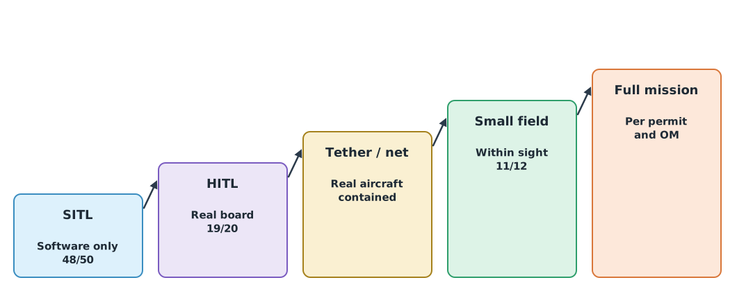
| Stage | What it tests | Risk if it fails |
|---|---|---|
| SITL | Mission logic, failsafes and links, using PX4 with Gazebo (make px4_sitl gz_x500) or ArduPilot with sim_vehicle.py | None |
| HITL | Real firmware on the real board, with a simulated world | Low |
| Tethered or in a net cage | Real aircraft and sensors in a controlled space | Limited |
| Small field test | A short mission within sight, with a pilot ready to take over | Moderate |
| Full mission | Under the permit and operations manual | Controlled by risk assessment |
Every stage tests both normal and abnormal cases, such as a hung companion computer, GNSS loss, control link loss and low battery, checking that failsafes and geofences behave as configured. The PX4 documentation gathers these failsafe settings on one page.
How many runs are enough?
A success rate from a few runs is highly uncertain, so report it with a confidence interval, as in UAT 106.
Example 1 Success rate at each stage
import math
from scipy import stats

for stage, runs, ok in (("SITL", 50, 48), ("HITL", 20, 19), ("field", 12, 11)):
    ci = stats.binomtest(ok, runs).proportion_ci(confidence_level=0.95)
    print(f"{stage:<6} {ok}/{runs} = {ok / runs:.0%}  95% CI [{ci.low:.0%}, {ci.high:.0%}]")

reliability, confidence = 0.90, 0.95
n = math.ceil(math.log(1 - confidence) / math.log(reliability))
print(f"to show >= {reliability:.0%} success with {confidence:.0%} confidence and no failures: {n} runs in a row")
SITL 48/50 = 96% 95% CI [86%, 100%]
HITL 19/20 = 95% 95% CI [75%, 100%]
field 11/12 = 92% 95% CI [62%, 100%]
to show >= 90% success with 95% confidence and no failures: 29 runs in a rowEleven successes in twelve field runs (92%) sounds good, but the confidence interval reaches down to about 62%. To show a success rate of at least 90% with 95% confidence requires 29 consecutive successes with no failure. This number helps plan the number of test flights, and shows which conclusions cannot yet be claimed.
Run-time assurance
AI and path planners are too complex to prove safe in every situation. The run-time assurance (RTA) approach of ASTM F3269-21 therefore adds a simple, verifiable monitor that checks whether the system is still within a safe envelope and, if it is about to leave it, switches to a safe controller such as braking, holding or returning home.
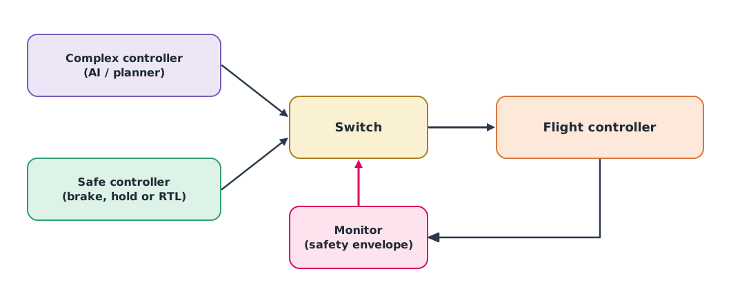
Example 2 A monitor ahead of the geofence
The complex controller accelerates the drone towards a geofence at 100 m. The monitor keeps a 5 m margin and computes stopping distance with 0.3 s latency and 2.5 m/s² braking.
fence, margin, latency, brake, dt = 100.0, 5.0, 0.3, 2.5, 0.1
x, v, t, mode = 80.0, 4.0, 0.0, "complex"
while t < 10:
    stop = v * latency + v * v / (2 * brake)
    if mode == "complex" and x + stop >= fence - margin:
        mode = "safe"
        print(f"switch to safe controller at t = {t:.1f} s, x = {x:.1f} m, v = {v:.1f} m/s")
    v = min(v + 0.5 * dt, 8.0) if mode == "complex" else max(v - brake * dt, 0.0)
    x += v * dt
    t = round(t + dt, 1)
    if mode == "safe" and v == 0:
        break
print(f"stopped at x = {x:.1f} m, {fence - x:.1f} m before the fence")
switch to safe controller at t = 2.0 s, x = 89.0 m, v = 5.0 m/s
stopped at x = 93.8 m, 6.2 m before the fenceThe monitor does not need to know what the complex controller is thinking, only that continuing would not leave room to stop, so it is far easier to verify than the AI. A real system should also keep the geofence in the flight controller as a further layer, in case the whole companion computer fails.
Before flying for real
- Law: beyond-visual-line-of-sight (BVLOS) flight in Thailand is covered by CAAT guidance CAAT-GM-UAS-PDRA101 (May 2025), which specifies a predefined risk assessment, operations manual, training and emergency response plan. Check the latest issue before every application
- Operating procedures under ISO 21384-3 and the organisation’s operations manual
- Systems using ML: EASA’s AI Concept Paper Issue 2 (2024) sets out guidance for Level 1 and 2 machine learning applications, a good reference frame for writing safety evidence
- A pilot ready to take over at every real-flight stage, with a tested mode switch or kill switch
Module lab
Lab: a complete autonomous survey mission
- Combine the work of modules 1–4 into one mission: take off, fly a survey route, avoid obstacles using the camera and range sensor, and return to land.
- Write a five-stage test plan with measurable pass criteria before testing, and a list of abnormal cases to test.
- Test in SITL at least 30 times with random wind and obstacle positions, add a monitor like Example 2, and test a hung companion computer.
- Test in a cage or controlled area under the instructor’s supervision, with a pilot ready to take over.
- Report success rates with confidence intervals at every stage, the failures and fixes, and whether the system is ready for the next stage.
Common mistakes
Watch out
- Jumping from SITL to the field without HITL or a controlled area
- Testing only normal cases and not the failsafes
- Setting pass criteria after seeing results
- Reporting success rates without confidence intervals from a handful of runs
- Making the monitor as complex as the controller, so it cannot be verified
Summary
- Test as a ladder, SITL → HITL → controlled area → small field test → full mission, including abnormal cases at every stage
- Success rates need confidence intervals; showing at least 90% success at 95% confidence takes 29 consecutive successes
- Run-time assurance uses a simple monitor to switch to a safe controller before leaving the envelope
- Before flying for real, check the law and operations manual, and always have a pilot ready to take over
Check your understanding
- Which stage tests real firmware on the real board with a simulated world?
- To show at least 95% success with 95% confidence, how many consecutive successes are needed?
- A drone is at 90 m, flying 5 m/s with 0.2 s latency and 2.5 m/s² braking; the fence is at 100 m with a 3 m margin. Should the monitor switch yet?
- Why should the run-time assurance monitor be simple?
- Which CAAT guidance covers BVLOS flight using a predefined risk assessment?
Answers
- HITL
- Stopping distance m, so it would stop at 96 m, short of the m limit. It need not switch yet, but only 1 m remains
- So it can be checked and proven correct, unlike the complex controller
- CAAT-GM-UAS-PDRA101
Key formulas
| Consecutive successes needed | |
| Stopping check used by the monitor |
Key references
- PX4 Autopilot. Gazebo simulation. PX4 user guide (main). link
- PX4 Autopilot. Hardware in the loop simulation (HITL). PX4 user guide (main). link
- PX4 Autopilot. Safety configuration (failsafes). PX4 user guide (main). link
- ArduPilot Dev Team. SITL simulator (software in the loop). link
- ASTM International. (2021). Standard practice for methods to safely bound behavior of aircraft systems containing complex functions using run-time assurance (ASTM F3269-21). link
- European Union Aviation Safety Agency. (2024). EASA artificial intelligence concept paper issue 2: Guidance for Level 1 & 2 machine learning applications. link
- สำนักงานการบินพลเรือนแห่งประเทศไทย. (2568). แนวปฏิบัติในการขอปฏิบัติการบินอากาศยานซึ่งไม่มีนักบินโดยใช้การประเมินความเสี่ยงที่เป็นไปตามเงื่อนไขที่กำหนดสำหรับการบินเกินกว่าระยะสายตา (CAAT-GM-UAS-PDRA101 ปรับปรุงครั้งที่ 00). link
- International Organization for Standardization. (2023). Unmanned aircraft systems — Part 3: Operational procedures (ISO 21384-3:2023). link
Further reading
Study the assigned knowledge units in advance, review media and take the module quiz
Developing simulations and connecting SITL
PX4 SITL + Gazebo
MAVSDK
Choosing and comparing drone simulators
Holding a track in simulated wind
Dropping and restoring a simulated link
In class / field
Intensive lab and field practice recorded in a lab notebook
Learning evidence: Lab notebook signed by the instructor